
Retractable and extendable material loader apparatus for directing material onto a conveyor

a material loader and conveyor technology, applied in the direction of loading/unloading, chutes, transportation and packaging, etc., can solve the problems of increased bulk material spillage, opening of the second, and the downstream loader cannot be positioned in close proximity to the conveying surface, so as to improve the health and safety conditions and improve the operation safety conditions

Active Publication Date: 2008-10-21
BENETECH INC
View PDF16 Cites 5 Cited by
  • Summary
  • Abstract
  • Description
  • Claims
  • Application Information

AI Technical Summary

Benefits of technology

[0007]The retractable and extendable material loader apparatus of the present invention overcomes the disadvantages associated with the prior art second, downstream material loader that directs material onto a conveying surface of a conveyor downstream from a first, upstream loader. The apparatus provides improved environmental conditions over the current art, improved health and safety conditions of personnel over the current art, and improved operational safety conditions in respect to explosion risk over the current art. This is accomplished by providing the material loader apparatus with a retractable and extendable length where the length can be extended to discharge material onto a conveying surface, and can be retracted to provide adequate clearance for material discharged onto the conveying surface by the first, upstream loader. The material loader apparatus of the invention thereby overcomes the disadvantages associated with prior art loader apparatus that direct bulk material from two or more supply conveyors, through two or more loader apparatus to a single receiving conveyor.
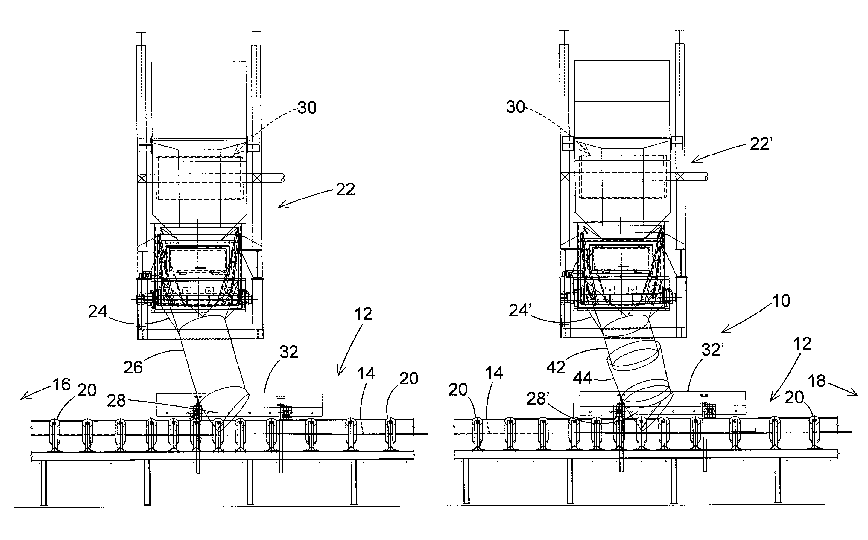
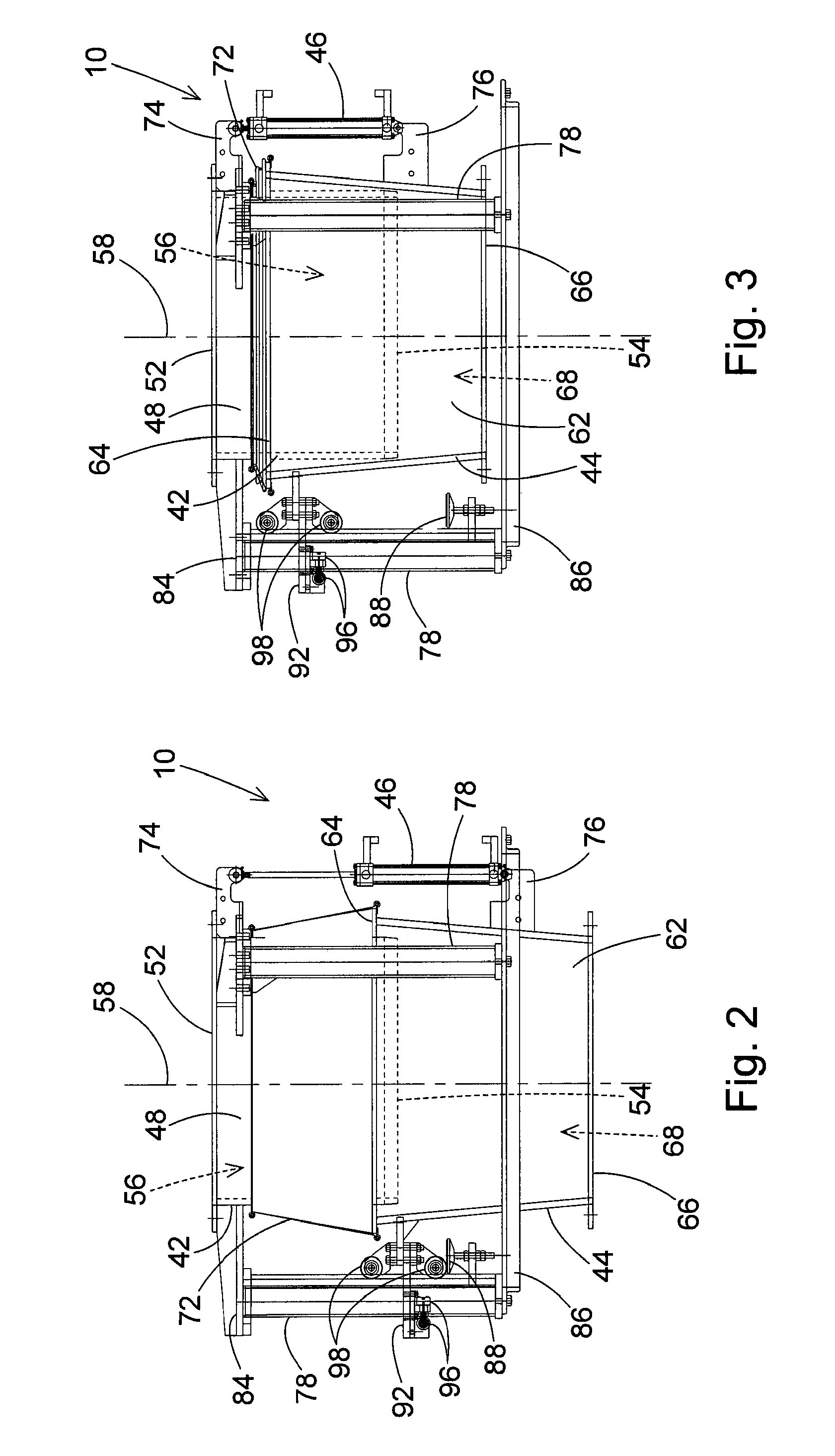
[0015]In operation, the retractable and extendable material loader is positioned along a conveyor in a downstream direction from at least one other material loader positioned upstream along the conveyor. When the other upstream material loader is not loading material on the conveyor and the retractable and extendable material loader is loading material on the conveyor, the actuators are operated to extend the lower tubular section from the upper tubular section. This positions the bottom opening of the lower tubular section in close proximity to the conveying surface of the conveyor. Bulk material is then loaded onto the conveying surface of the conveyor through the upper tubular section and the extended lower tubular section. The positioning of the lower tubular section in close proximity to the conveying surface reduces the potential for spillage of the material as it exits the extended lower tubular section and contacts the moving conveying surface.

Problems solved by technology

The faster speed of the material impacting the conveying surface can result in spillage of the bulk material from the sides of the conveying surface.
The need to position the bottom exit opening of the tubular loader in close proximity to the conveying surface presents problems when two or more conveyors discharge bulk material to two or more tubular loaders that direct the material to a single receiving conveyor.
However, the bottom, outlet opening of the second, downstream loader cannot be positioned in close proximity to the conveying surface of the receiving conveyor without coming into contact with material loaded onto the conveying surface by the upstream loader.
The need to position the bottom outlet opening of the second, downstream loader at a higher position above the conveying surface presents the problem of increased spillage of the bulk material directed through the second, downstream loader onto the conveying surface.

Method used


Image

  • Retractable and extendable material loader apparatus for directing material onto a conveyor
  • Retractable and extendable material loader apparatus for directing material onto a conveyor
  • Retractable and extendable material loader apparatus for directing material onto a conveyor

Examples


Embodiment Construction

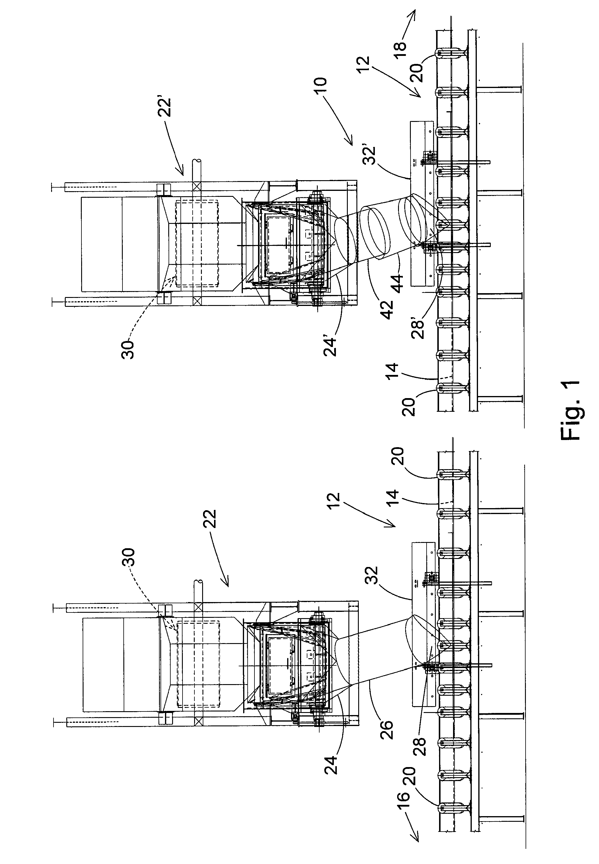
[0025]FIG. 1 is a schematic representation of one operative environment of the retractable and extendable material loader apparatus 10 of the present invention. It should be understood that the environment of FIG. 1 is only one example of an environment in which the apparatus may be used. There are other environments where the apparatus of the invention is equally well suited for use, and FIG. 1 should not be interpreted as the only operative environment in which the apparatus of the invention may be used.

[0026]A schematic representation of a conveyor 12 having a belt conveying surface 14 is shown in FIG. 1. The conveyor 12 is any conventional design of a belt conveyor that conveys bulk material in a downstream direction from an upstream end 16 of the conveyor shown to the left of FIG. 1, to a downstream end 18 of the conveyor shown to the right in FIG. 1. The conveyor 12 is basically comprised of a frame that supports a plurality of rollers 20. The rollers 20 are arranged to suppor...


PUM


Abstract

A retractable and extendable material loader that directs material onto a conveying surface of a belt conveyor has a retractable and extendable tubular length where the length of the loader is extended to direct material through the loader onto the conveyor, and a length of the loader is retracted when the loader is not directing material onto the conveyor to provide adequate clearance for material loaded onto the conveyor by another loader located upstream of the retractable and extendable loader. The apparatus provides improved environmental conditions over the current art, improved health and safety conditions of personnel over the current art, and improved operational safety conditions in respect to explosion risk over the current art.

Description

BACKGROUND OF THE INVENTION[0001]1. Field of the Invention[0002]The present invention pertains to a bulk material loader that directs material onto a conveying surface of a belt conveyor. In particular, the present invention is a material loader that has a retractable and extendable tubular length where the length of the loader is extended to direct material through the loader onto the moving belt surface of a conveyor, and the length of the loader is retracted when the loader is not directing material onto the conveyor to provide adequate clearance for material loaded onto the conveyor by another loader located upstream of the conveyor.[0003]2. Description of the Related Art[0004]The transporting of bulk material, for example coal, from one area to another often involves the transfer of a stream or flow of the material from two or more conveyors onto another, single conveyor. In the transfer of the material from one conveyor to a second conveyor, it is often necessary that the mate...

Claims


Application Information

Patent Timeline
IPC IPC(8): B65G11/14
CPCB65G11/146B65G47/44B65G65/28B65G69/181
Inventor CLARK, GREGORY A.ADEL, SIDWESTFALL, RONALD A.
Owner BENETECH INC
Learn More