Plasma processing apparatus and plasma processing method

a processing apparatus and plasma technology, applied in the direction of vacuum evaporation coating, electrolysis components, coatings, etc., can solve the problems of disadvantageous use of electromagnets and lowering the overall working efficiency of semiconductor processing, and achieve the effect of simple mechanism and ease of semiconductor wafer treatmen

Active Publication Date: 2008-10-21
SHIN ETSU CHEM CO LTD +1
View PDF10 Cites 37 Cited by
  • Summary
  • Abstract
  • Description
  • Claims
  • Application Information

AI Technical Summary

Benefits of technology

[0011]It is therefore an object of the present invention to provide a plasma processing apparatus which is able to adaptively set or control the state of a multiple magnetic field in accordance with a variety of plasma processing operations thereby to make it possible to ease the semiconductor wafer treatment with a simple mechanism.
[0012]Another object of the present invention is to provide a method of processing a work piece substrate in order to adaptively set or control the state of a multiple magnetic field depending on a variety of plasma processing operations, whereby the substrate is able to be easily treated with a simple mechanism.

Problems solved by technology

However, according to the research of the inventors of the instant application it was discovered that there are two contradictory instances in terms of etch rate uniformity across the wafer's surface.
However, the use of electromagnets is disadvantageous due to their high power consumption and bulkiness.
However, A large loading machine is required to mount and dismount permanent magnets on and from the processing apparatus to perform the start / stop control, and accordingly, this involves a long time to operate the machine, resulting in a lowering of the overall working efficiency of semiconductor processing.

Method used


Image

  • Plasma processing apparatus and plasma processing method
  • Plasma processing apparatus and plasma processing method
  • Plasma processing apparatus and plasma processing method

Examples


first embodiment

[0048]A reference is made to FIG. 3, wherein there is shown the present invention. According to the instant embodiment, the inner magnetic field generating portion 22 is provide with a plurality of magnetic segments 31 which are respectively magnetized in circumferential directions relative to the center of the vacuum chamber 1. On the other hand, the outer magnetic field generating portion 23 is provide with a plurality of magnetic segments 33 which are respectively magnetized in radial directions relative to the center of the vacuum chamber 1.

[0049]More specifically, as shown in FIG. 3(a), the magnetic segments 31 of the inner magnetic field generating portion 22 are respectively magnetized in the circumferential directions with the magnetic poles thereof being alternated, and have respectively magnetic material piece (i.e., block) therebetween. On the other hand, the magnetic segments 33 of the outer magnetic field generating portion 23 are respectively magnetized in radial direc...

second embodiment

[0053]Referring to FIGS. 4(a) to 4(c), there is schematically illustrated the present invention.

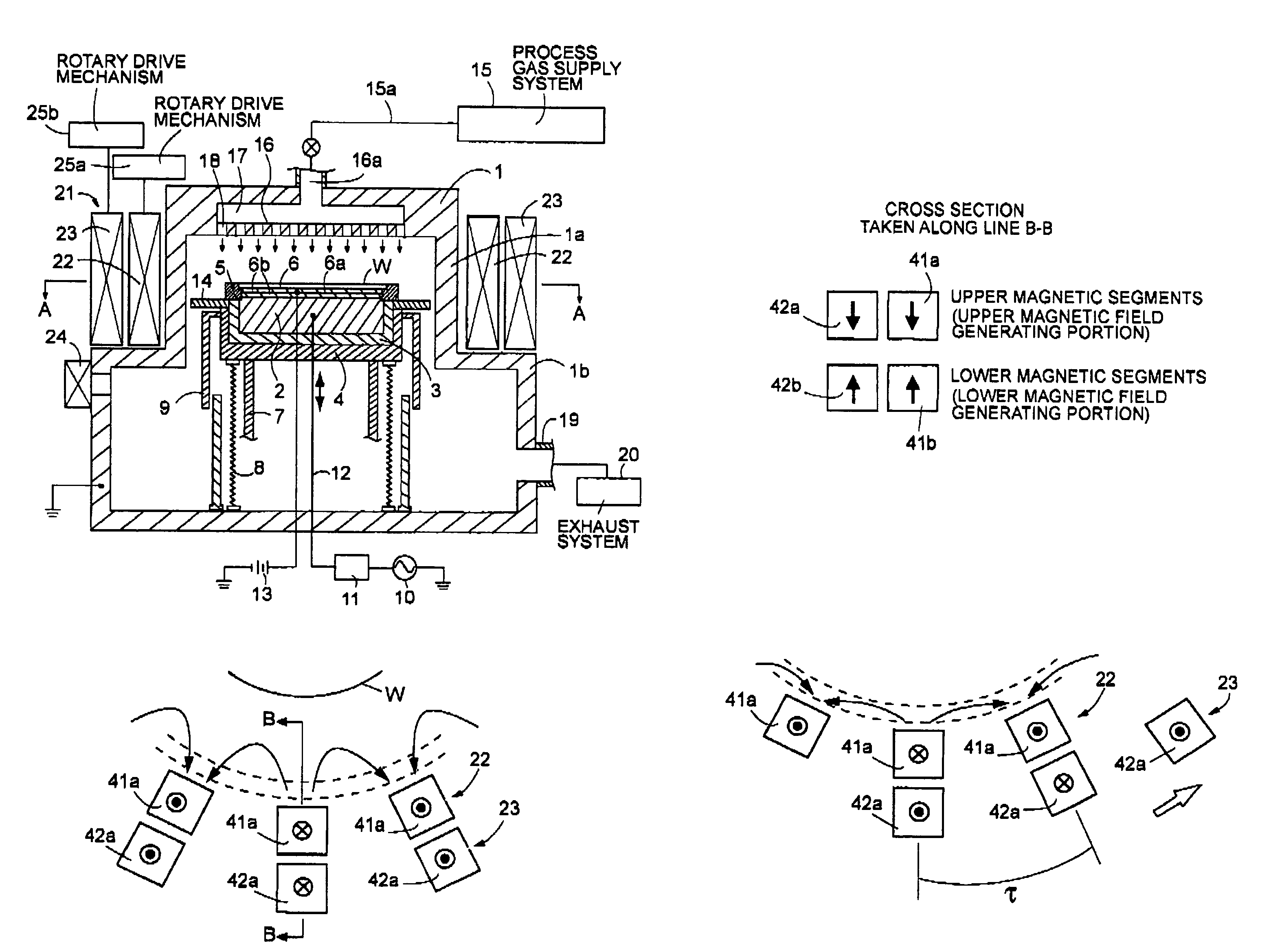
[0054]The magnetic field generator of the second embodiment, which corresponds to the magnetic field generator 21 of FIG. 1, is compressed of an inner and outer magnetic field generating portions 22 and 23 as with the first embodiment. However, the second embodiment differs from the first embodiment in that each of the inner and outer magnetic field generating portions 22 and 23 is divided into an upper and lower magnetic field generating portions with spacing therebetween.

[0055]As shown in FIG. 4(a), the inner magnetic field generating portion 22 comprises a plurality of upper magnetic segments 41a, and likewise, the outer magnetic field generating portion 23 comprises a plurality of upper magnetic segments 42a. These upper magnetic segments 41a and 42a are respectively provided circumferentialy around the vacuum chamber 1 (see FIG. 1) with a predetermined interval therebetween and with ...


PUM

PropertyMeasurementUnit
frequencyaaaaaaaaaa
frequencyaaaaaaaaaa
frequencyaaaaaaaaaa

Abstract

Disclosed is a plasma processing apparatus and a plasma processing method. A substrate to be processed is accommodated in a vacuum chamber within which a plasma generator is provided so as to generate plasma for use in performing plasma processing on the substrate. Outside the vacuum chamber provided is a magnetic field generator for generating a multi-pole magnetic field at the periphery of the substrate. The magnetic field generator comprises an inner ring-shaped magnetic field generating portion and an outer ring-shaped magnetic field generating portion, both of which are provided outside the vacuum chamber in a concentric relationship with the vacuum chamber and are independently rotatable with each other.

Description

BACKGROUND OF THE INVENTION[0001]1. Field of the Invention[0002]The present invention relates generally to an apparatus and method for implementing plasma processing on a work piece substrate such as a semiconductor wafer or the like.[0003]2. Description of Related Art[0004]In the field of manufacturing semiconductor devices, a semiconductor treatment apparatus is known for generating magnetron plasma in a vacuum chamber (viz., process chamber). The plasma thus generated is allowed to act on a work piece such as a semiconductor wafer positioned within the vacuum chamber whereby a desired treatment process such as etching and film forming, etc. is performed.[0005]In order to attain satisfactory results, it is necessary to maintain the plasma in a state optimized for a particular process. For this purpose, the magnetron plasma processing apparatus is provided with a magnetic field generator which controls or confines plasma in a desired state.[0006]In order to effectively control or c...

Claims


Application Information

Patent Timeline
Patent Type & Authority Patents(United States)
IPC IPC(8): H01L21/00C23C16/00
CPCH01J37/32623H01J37/3266H01J37/32688H01L21/31116
Inventor MIYATA, KOJISATO, TETSUJI
Owner SHIN ETSU CHEM CO LTD
Why Eureka
Try Eureka