Vehicle cruise control system

a technology of vehicle cruise control and control system, which is applied in the direction of brake system, process and machine control, instruments, etc., can solve the problems of switching operations required in order to achieve both setting the cruising speed setting and starting the following cruise control, and the switch operation required in order to achieve both setting the cruising speed setting. achieve the effect of improving the interoperability of shifting between the vehicle speed regions

Inactive Publication Date: 2008-10-21
NISSAN MOTOR CO LTD
View PDF27 Cites 18 Cited by
  • Summary
  • Abstract
  • Description
  • Claims
  • Application Information

AI Technical Summary

Benefits of technology

[0009]Accordingly, one object of the present invention is to provide a vehicle cruise control system in which operability with respect to shifting between vehicle speed regions is improved.

Problems solved by technology

Thus, the switch operations required in order to accomplish both shifting to the higher speed region and setting the cruising speed setting to the desired value are complicated in the conventional preceding vehicle following cruise control system.
Thus, the switch operations required in order to accomplish both starting the following cruise control and setting the cruising speed setting to the desired value are complicated in the conventional preceding vehicle following cruise control system.

Method used


Image

  • Vehicle cruise control system
  • Vehicle cruise control system
  • Vehicle cruise control system

Examples


second embodiment

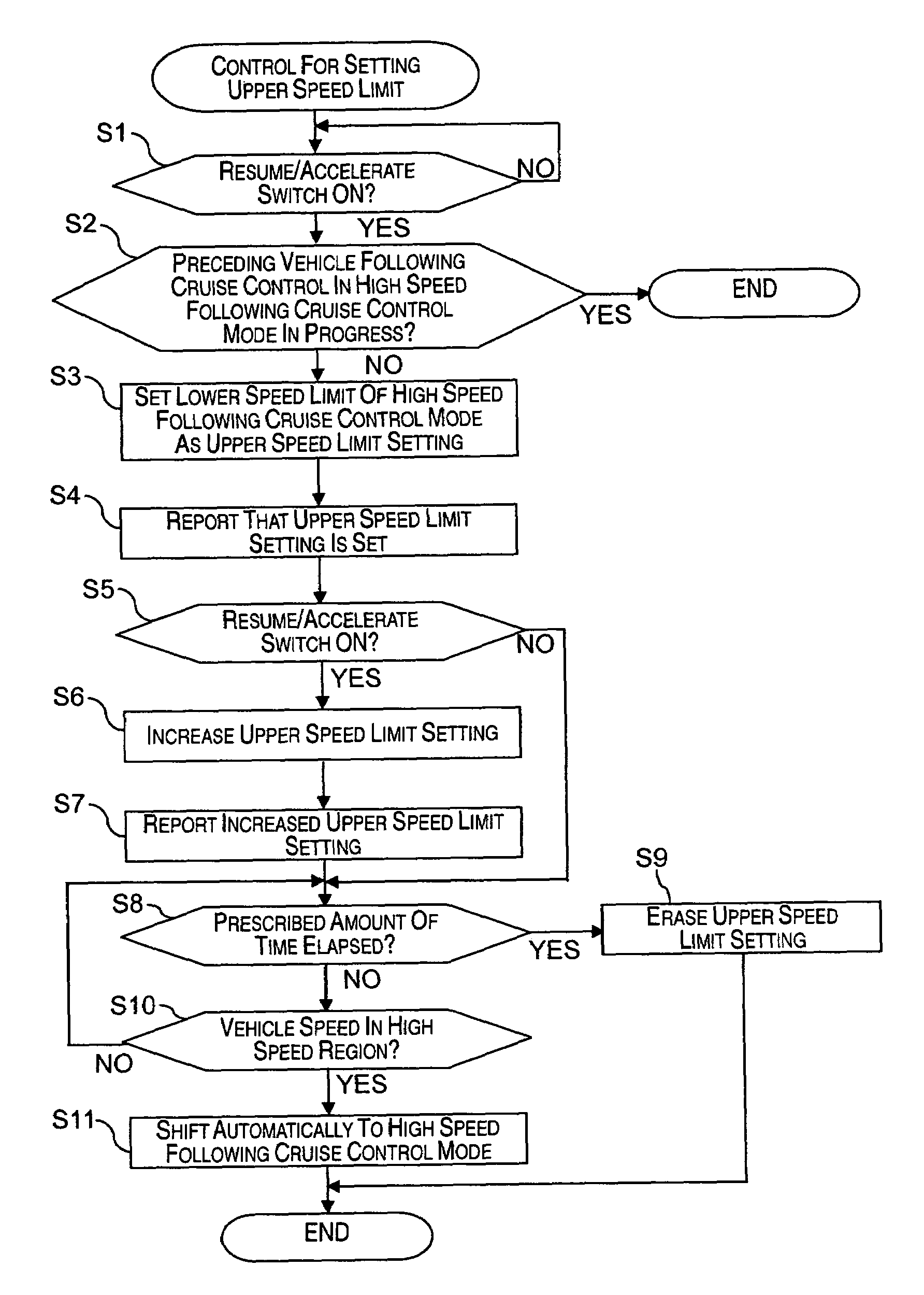
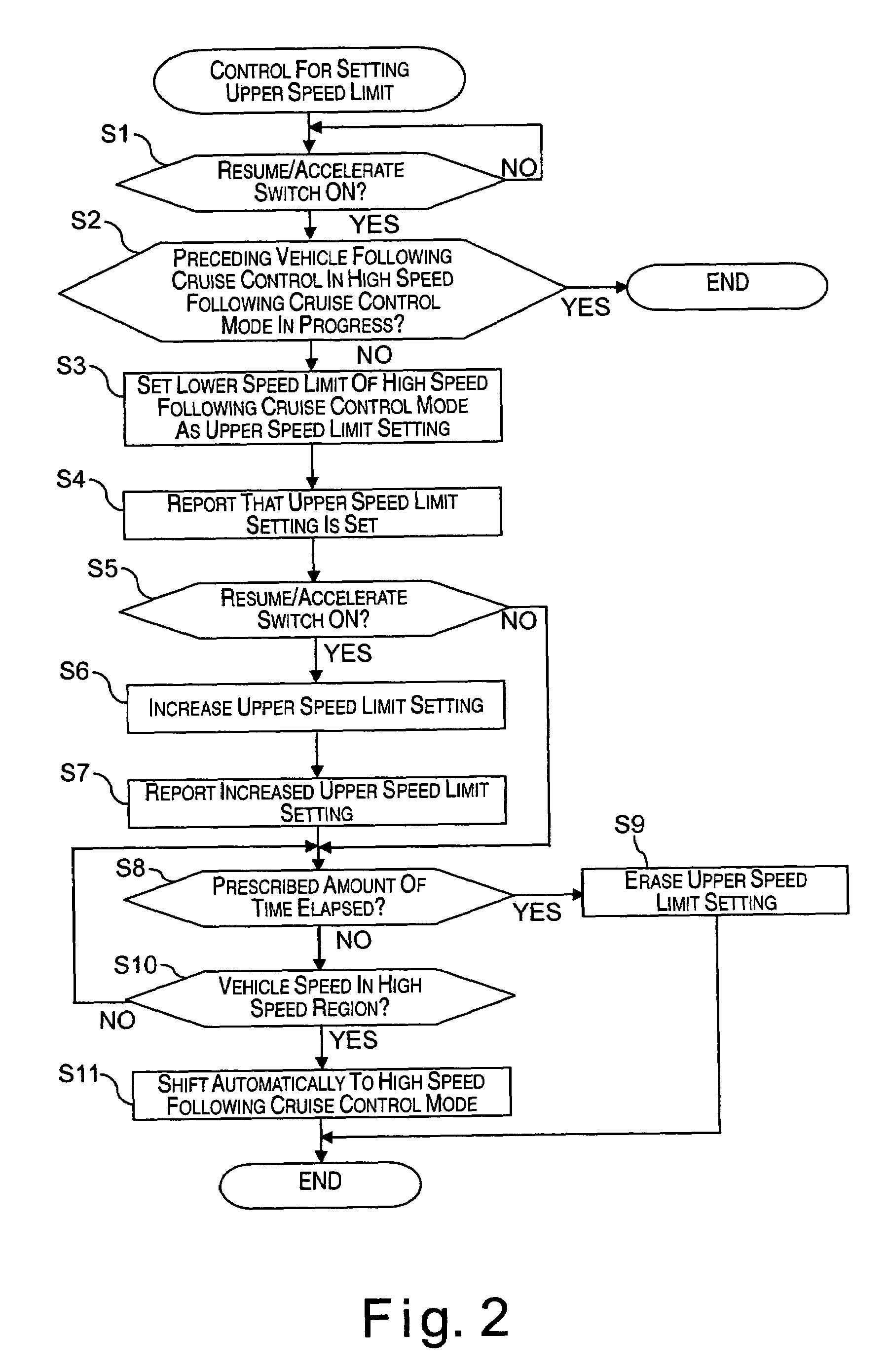
[0043]Referring now to FIG. 6, a vehicle cruise control system in accordance with a second embodiment will now be explained. In view of the similarity between the first and second embodiments, the parts of the second embodiment that are identical to the parts of the first embodiment will be given the same reference numerals as the parts of the first embodiment. Moreover, the descriptions of the parts of the second embodiment that are identical to the parts of the first embodiment may be omitted for the sake of brevity.

[0044]The vehicle cruise control system in the second embodiment differs from the vehicle cruise control system of the first embodiment in that the preceding vehicle following cruise control is executed only in a prescribed vehicle speed region in the second embodiment while the vehicle cruise control system of the first embodiment was configured to execute the preceding vehicle following control in the total range of vehicle speeds and a unique preceding vehicle follo...

third embodiment

[0052]Referring now to FIG. 7, a vehicle cruise control system in accordance with a third embodiment will now be explained. In view of the similarity between the first and third embodiments, the parts of the third embodiment that are identical to the parts of the first embodiment will be given the same reference numerals as the parts of the first embodiment. Moreover, the descriptions of the parts of the third embodiment that are identical to the parts of the first embodiment may be omitted for the sake of brevity.

[0053]The vehicle cruise control system of the third embodiment differs from the vehicle cruise control system of the first embodiment in that the vehicle cruise control system of the third embodiment is arranged as an ASCD (auto speed control device) that is configured to execute a constant speed cruise control such that the host vehicle travels in a constant-speed state at a cruising speed setting (hereinafter called “cruising speed setting”) in an ASCD mode regardless o...


PUM


Abstract

A vehicle cruise control system is provided that comprises a vehicle speed detecting section, a cruise control section, and a cruising speed setting section. The vehicle speed detecting section is configured and arranged to detect a speed of a host vehicle. The cruise control section is configured to execute a first prescribed cruise control such that the host vehicle travels in a constant-speed state at a cruising speed setting when the host vehicle is traveling in a first prescribed speed region. The cruising speed setting section is configured to set the cruising speed setting when the host vehicle is traveling in a vehicle speed region other than the first prescribed speed region.

Description

CROSS-REFERENCE TO RELATED APPLICATIONS[0001]This application claims priority under 35 U.S.C. § 119 to Japanese Patent Application No. 2004-209972. The entire disclosure of Japanese Patent Application No. 2004-209972 is hereby incorporated herein by reference.BACKGROUND OF THE INVENTION[0002]1. Field of the Invention[0003]The present invention relates to a vehicle cruise control system.[0004]2. Background Information[0005]Japanese Laid-Open Patent Publication No. 2002-234358 discloses a conventional preceding vehicle following cruise control system in a total range of vehicle speeds (0 to 100 km / h) in which a preceding vehicle following cruise control (i.e., a following cruise control) is executed is divided into a plurality of vehicle speed regions. The conventional preceding vehicle following cruise control system is configured to execute the following cruise control so that a host vehicle follows a preceding vehicle in a manner corresponding to the vehicle speed region in which t...

Claims


Application Information

Patent Timeline
Patent Type & Authority Patents(United States)
IPC IPC(8): B60T8/32
CPCB60K31/0008B60W30/16
Inventor SHIMA, TAKASHI
Owner NISSAN MOTOR CO LTD
Why Eureka
Try Eureka