Hose reel automatic storage

a technology of automatic storage and hose reel, which is applied in the direction of thin material handling, gymnasium, construction, etc., can solve the problems of u.s. patent no. 3,392,738, the device cannot accommodate the head of a standard cleaner, and the hose is removed from the pool and stored

Inactive Publication Date: 2008-10-28
PANSINI ANDREW L
View PDF17 Cites 2 Cited by
  • Summary
  • Abstract
  • Description
  • Claims
  • Application Information

AI Technical Summary

Problems solved by technology

One problem associated with any type of pool cleaner is removal of the hose from the pool and storage of the hose when the cleaner is not in use.
The device of U.S. Pat. No. 3,392,738, would not effectively return to the pool, because it does not disclose a means for turning off the cleaner while the rotation jets are in operation.
Also, the device cannot accommodate the head of a standard cleaner.
If such a cleaner head were pulled into the device, it would be lying on its side, with no wall or floor contact for the wheels, and would not be able to aid in unwinding the hose reel.
Finally, the device does not lend itself for automation.

Method used


Image

  • Hose reel automatic storage
  • Hose reel automatic storage
  • Hose reel automatic storage

Examples


first embodiment

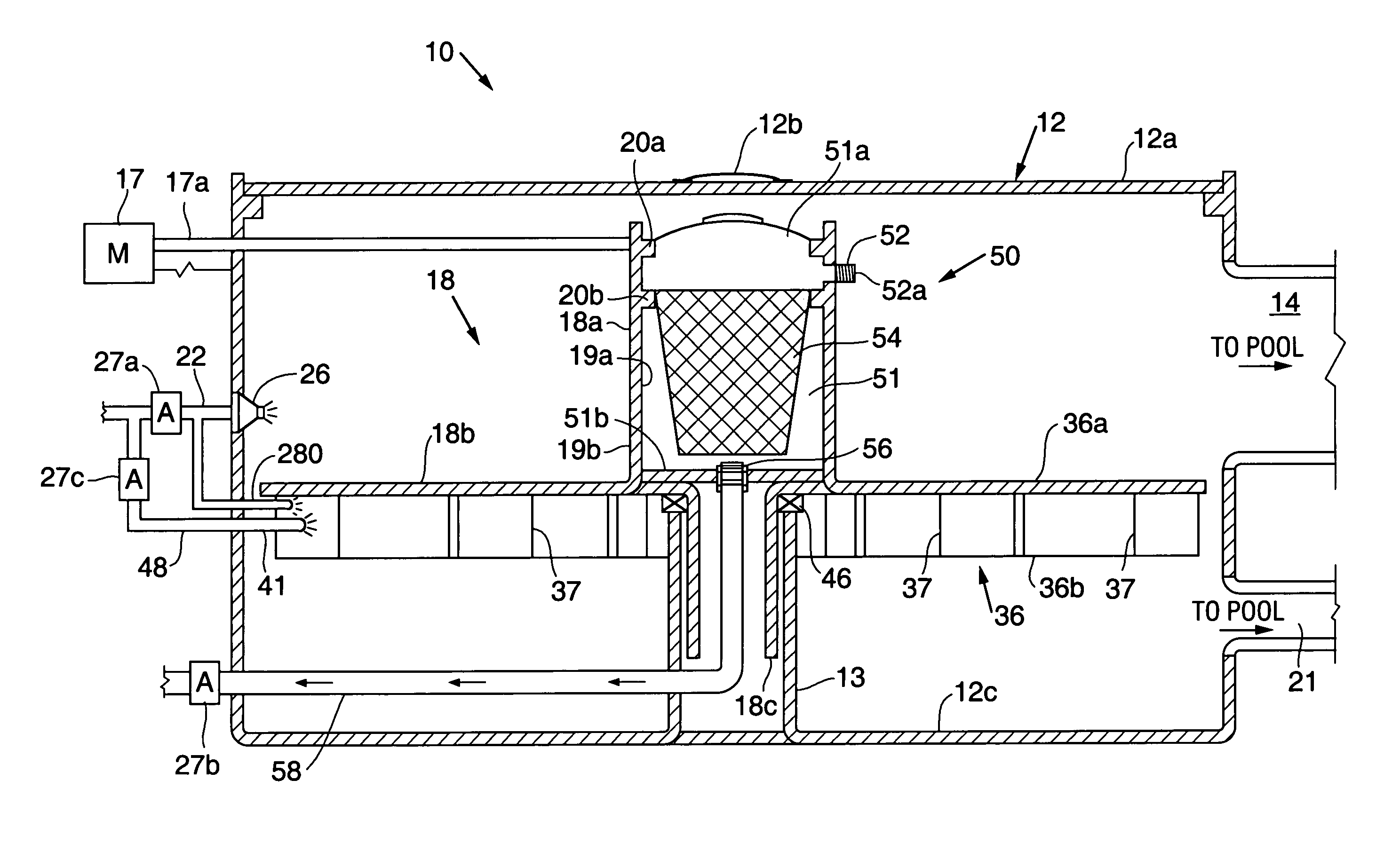
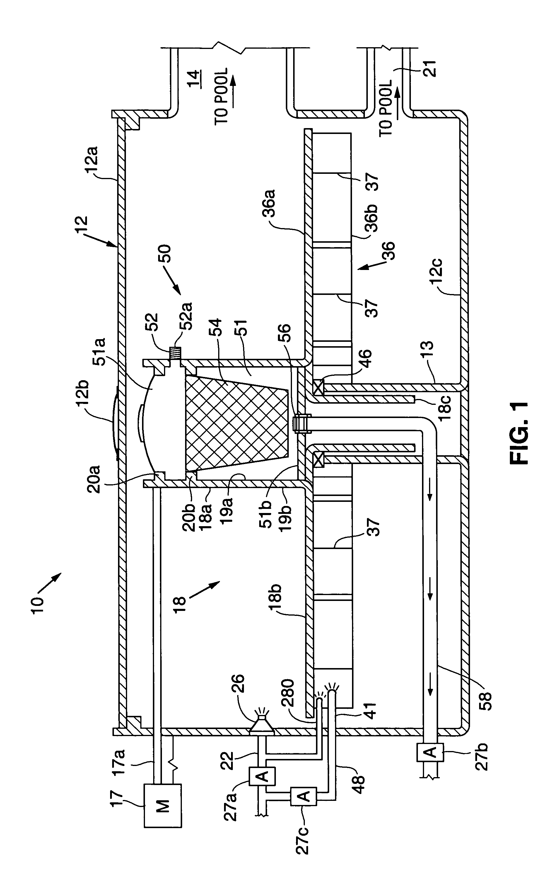
[0025]With reference to FIGS. 1-3, according to the invention, device 10 includes a tank 12 having a removable cover plate 12a, with a handle 12b; a hollow, rotatable hose reel 18 having an upper circular drum portion 18a, a circular base portion 18b, adapted to support hose 11 when it is wound around drum portion 18a, and a lower cylindrical portion 18c, extending vertically downwardly from base portion 18b; and a circular, rotatable water wheel 36 connected to the base portion 18b, and having a central hole formed therethrough. Tank 12 further includes a drain passageway 21 connecting the lower portion of tank 12, where water wheel 36 is located, to pool P and a support cylinder 13 concentric with the circular base portion 18b. A bearing 46 supports circular base portion 18b, on the cylinder 13.

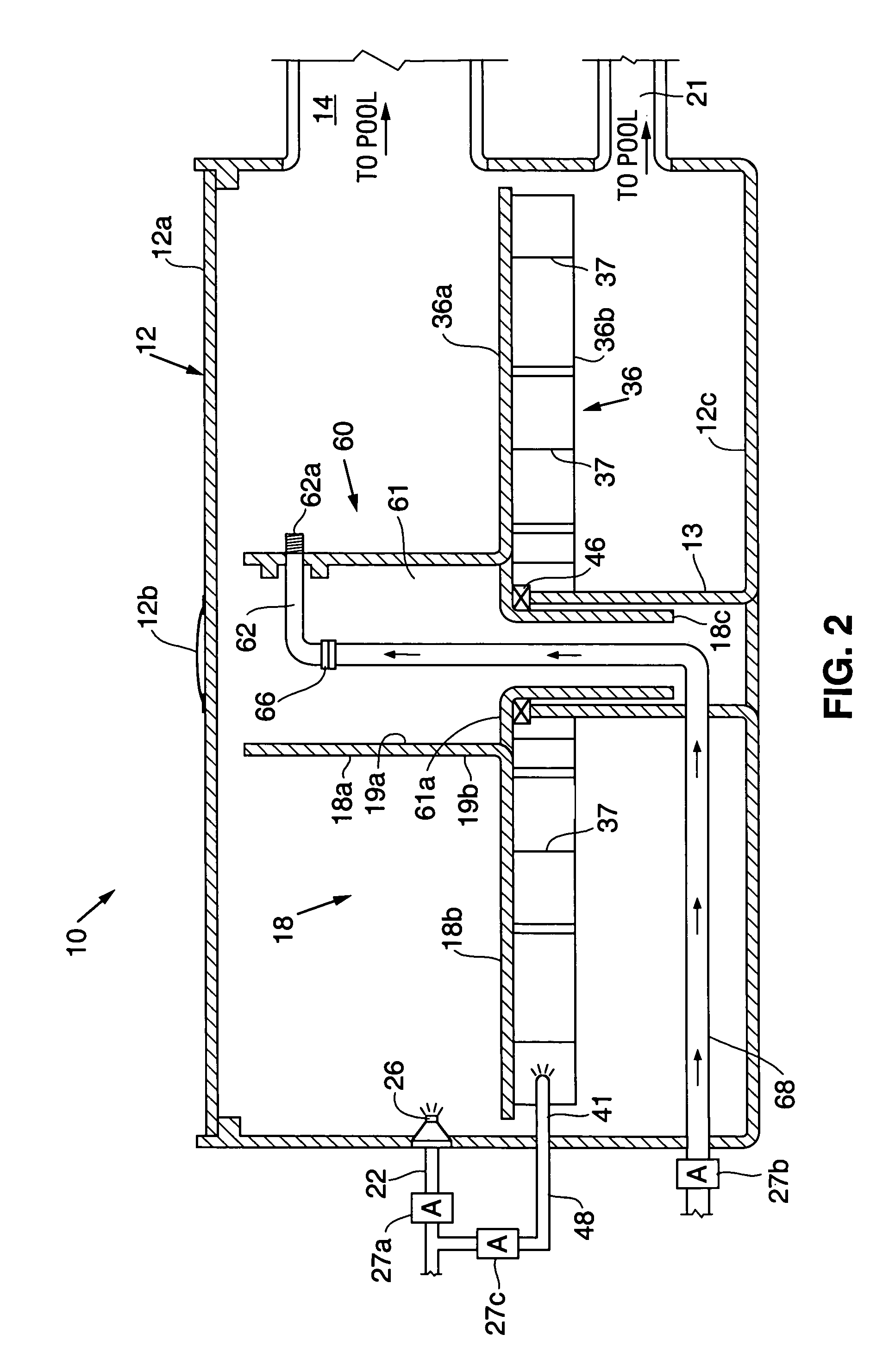
[0026]Tank 12 contains either suction cleaner 50 (FIG. 1) or pressure cleaner 60 (FIG. 2). Tank 12 is connected to swimming pool P through a horizontally extending passageway 14. Passageway...

second embodiment

[0032]When suction cleaner 50 or pressure cleaner 60 is in use, hose 11 is relocated to a second position in pool 16 (illustrated in FIG. 3 and in FIG. 7, with reference to the second embodiment), as follows. Pipe 22 is connected to a pressurized water source (not shown) at one end and a blow out jet nozzle 26 at the other end. Pipe 22 preferably has a diameter of about ¾ inch. Blow out jet nozzle 26 is comparable to a fire hose nozzle. To unwind hose 11 from hose reel 18 and move hose 11 from the first storage position to a second position in pool 16, the pressurized water source is turned on via solenoid valve 27a, and water travels through pipe 22 and out blow out jet nozzle 26. The water is directed toward the cleaner head (not shown) of hose 11, and flushes cleaner head and hose 11 out of tank 12, through passageway 14 and into pool 16. This causes hose reel 18 to rotate in a first direction, and unwinds hose 11 from hose reel 18. This allows hose 11 to be moved from the first ...


PUM


Abstract

A device for moving the hose of an automatic pool cleaner in and out of a swimming pool using water power. The device includes a rotatable hose reel disposed within a tank spaced from the pool. In one embodiment, the tank communicates with the pool through an under-the-deck tunnel. In another, the tunnel extends from the tank and over the deck of the pool, for discharge into the pool. The hose reel is connected to a rotatable water wheel having vertically-oriented blades disposed around its circumference. To move the hose from the storage position into the pool, a stream of water from a blow out jet nozzle flushes the hose into the pool and rotates the hose reel in a first direction, causing the hose to unwind and travel into the pool. To move the hose from the pool back into the storage position, pressurized water is directed horizontally at the vertically-oriented blades of the water wheel, causing the water wheel and hose reel to rotate in a second direction to withdraw the hose from the pool and rewind the hose onto the hose reel.

Description

RELATED APPLICATION[0001]This is a continuation-in-part of U.S. application Ser. No. 10 / 078,802, filed Feb. 19, 2002, by Andrew L. Pansini, the inventor herein.BACKGROUND OF THE INVENTION[0002]1. Field of the Invention[0003]The present invention relates to an automatic storage device for use in connection with a swimming pool cleaner. More specifically, the invention relates to an automatic storage device for moving the hose of an automatic pool cleaner in and out of a swimming pool using water power. The device can be used with both conventional suction pool cleaners and conventional pressure pool cleaners. The device of the invention accommodates both under-the-deck installations, as might be incorporated into new pools during the course their construction, or over-the-deck installations which might be added to pre-existing pools, without disturbing the construction of the pools or their surrounding deck structure.[0004]2. Related Art[0005]Both suction and pressure-type pool clean...

Claims


Application Information

Patent Timeline
Patent Type & Authority Patents(United States)
IPC IPC(8): E04H4/00B08B3/00B65H75/44E04H4/16
CPCE04H4/1654E04H4/1681Y10T137/6918E04H4/1645
Inventor PANSINI, ANDREW L.
Owner PANSINI ANDREW L
Why Eureka
Try Eureka