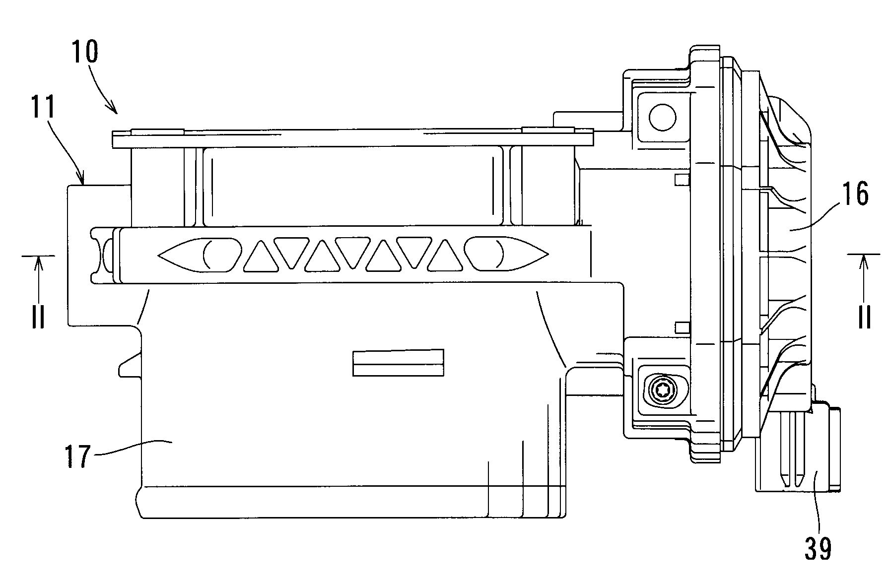
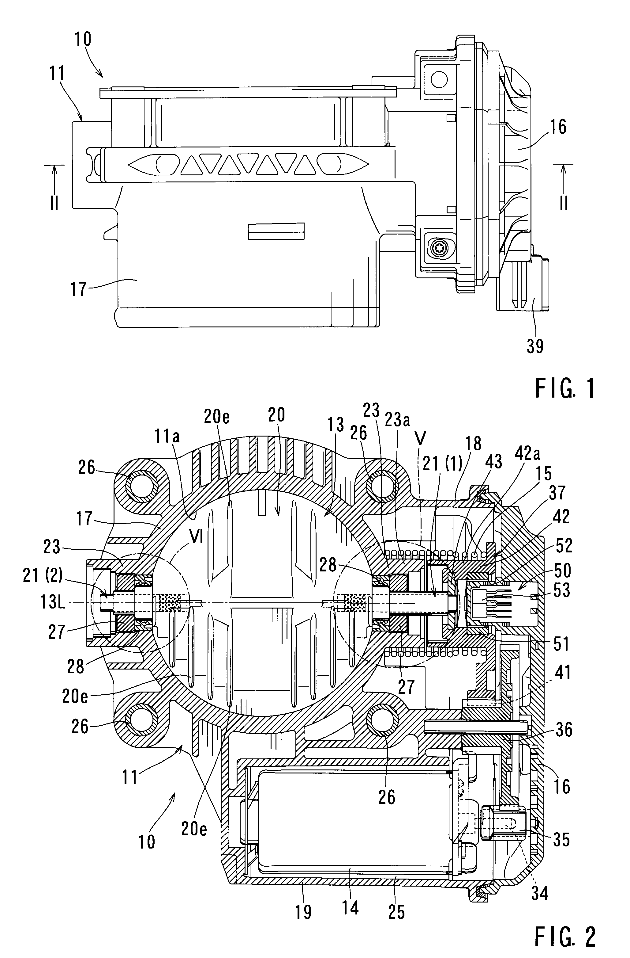
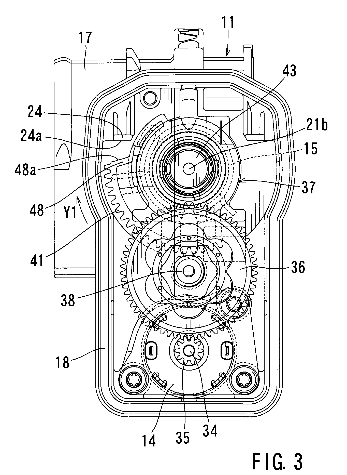
Butterfly valves and intake air control devices for internal combustion engines

a technology of intake air control device and butterfly valve, which is applied in the direction of engine controller, machine/engine, mechanical apparatus, etc., can solve the problems of low flowability of molten resin for molding the butterfly valve body around the throttle shaft, improper molding, and deformation of the butterfly valve in some cases

Inactive Publication Date: 2008-10-28
AISAN IND CO LTD +1
View PDF4 Cites 1 Cited by
  • Summary
  • Abstract
  • Description
  • Claims
  • Application Information

AI Technical Summary

Benefits of technology

[0007]A butterfly valve has a resin valve body and a shaft that includes a first shaft member and a second shaft member. The first and second shaft members are integrated with the valve body, while the first and second shaft members are spaced from each other in an axial direction by a predetermined distance. Therefore, during a molding process of the valve body, a flow path having a width corresponding to the distance between the first shaft member and the second shaft member can be ensured for the flow of the molten resin.

Problems solved by technology

Therefore, during the molding process, the flowability of a molten resin for molding the valve body around the throttle shaft may be low, and therefore, the quality of the butterfly valve may be degraded in some cases.
Therefore, in the region on the backside of the throttle shaft with respect to the direction of flow of the molten resin toward the throttle shaft, a cavity blank or a weld line may be formed to cause improper molding.
As a result, the quality of the throttle valve may be degraded.

Method used


Image

  • Butterfly valves and intake air control devices for internal combustion engines
  • Butterfly valves and intake air control devices for internal combustion engines
  • Butterfly valves and intake air control devices for internal combustion engines

Examples


Embodiment Construction

[0019]Each of the additional features and teachings disclosed above and below may be utilized separately or in conjunction with other features and teachings to provide improved butterfly valves and intake air control devices having such butterfly valves. Representative examples of the present invention, which utilize many of these additional features and teachings both separately and in conjunction with one another, will now be described in detail with reference to the attached drawings. This detailed description is merely intended to teach a person of skill in the art further details for practicing preferred aspects of the present teachings and is not intended to limit the scope of the invention. Only the claims define the scope of the claimed invention. Therefore, combinations of features and steps disclosed in the following detailed description may not be necessary to practice the invention in the broadest sense, and are instead taught merely to particularly describe representati...


PUM


Abstract

The present invention includes a butterfly valve that has a resin valve body and a shaft. The shaft includes a first shaft member and a second shaft member. The first and second shaft members are integrated with the valve body. The first and second shaft members are spaced from each other in an axial direction by a predetermined distance.

Description

[0001]This application claims priority to Japanese patent application serial number 2006-283736, the contents of which are incorporated herein by reference.BACKGROUND OF THE INVENTION[0002]1. Field of the Invention[0003]The present invention relates to butterfly valves. The present invention also relates to intake air control devices that have butterfly valves and are used for internal combustion engines.[0004]2. Description of the Related Art[0005]Japanese Laid-Open Patent Publication No. 2001-74156 teaches a known butterfly valve. This butterfly valve has a throttle shaft that is a one piece member integrated with a valve body by an insertion molding process. Therefore, during the molding process, the flowability of a molten resin for molding the valve body around the throttle shaft may be low, and therefore, the quality of the butterfly valve may be degraded in some cases. Thus, when the molten resin injected into a molding die flows in a diametrical direction with respect to the...

Claims


Application Information

Patent Timeline
Patent Type & Authority Patents(United States)
IPC IPC(8): F02D9/08
CPCF02D9/1065
Inventor ASANUMA, HIROSHINAKAMURA, TAKUJI
Owner AISAN IND CO LTD
Why Eureka
Try Eureka