Spacing part for cooling body and air-conditioner pad using same

A body and air-conditioning technology, applied in mattresses, applications, spring mattresses, etc., can solve the problems of low production convenience, complex mold structure, and high production cost, and achieve improved production convenience, simple mold structure, and improved convenience. Effect

Inactive Publication Date: 2010-12-22
ATEX CO LTD
View PDF0 Cites 0 Cited by
  • Summary
  • Abstract
  • Description
  • Claims
  • Application Information

AI Technical Summary

Problems solved by technology

[0004] However, the existing spacer a has the disadvantage of poor usability because its contact direction with the user's body is limited to the side of the surface material part b.
Furthermore, since a large load is supported on the end surface of the convex part c, as in Figure 20b As shown, it is easy to produce a large skew and be crushed
In such a state, the air will not be able to pass through the interior sufficiently, and even have the disadvantage of reducing the cooling effect of the body
In particular, when placed on soft bedding such as a mattress, the convex portion c will sink into the bedding, making it impossible to form an air flow path
[0005] Moreover, in the conventional spacer a, in order to form the air flow path, the hole d penetrating the horizontal direction is provided in the convex part c, so the mold structure of the spacer a is relatively complicated.
Therefore, the manufacturing cost of the mold for the spacer a is high, and at the same time, the life of the mold is short, and there are many defective products during molding, which has the disadvantage of low production convenience.

Method used


Image

  • Spacing part for cooling body and air-conditioner pad using same
  • Spacing part for cooling body and air-conditioner pad using same
  • Spacing part for cooling body and air-conditioner pad using same

Examples


Embodiment Construction

[0071] In order to make the above-mentioned and other objects, features and advantages of the present invention more comprehensible, the preferred embodiments of the present invention are specifically cited below, together with the accompanying drawings, and are described in detail as follows:

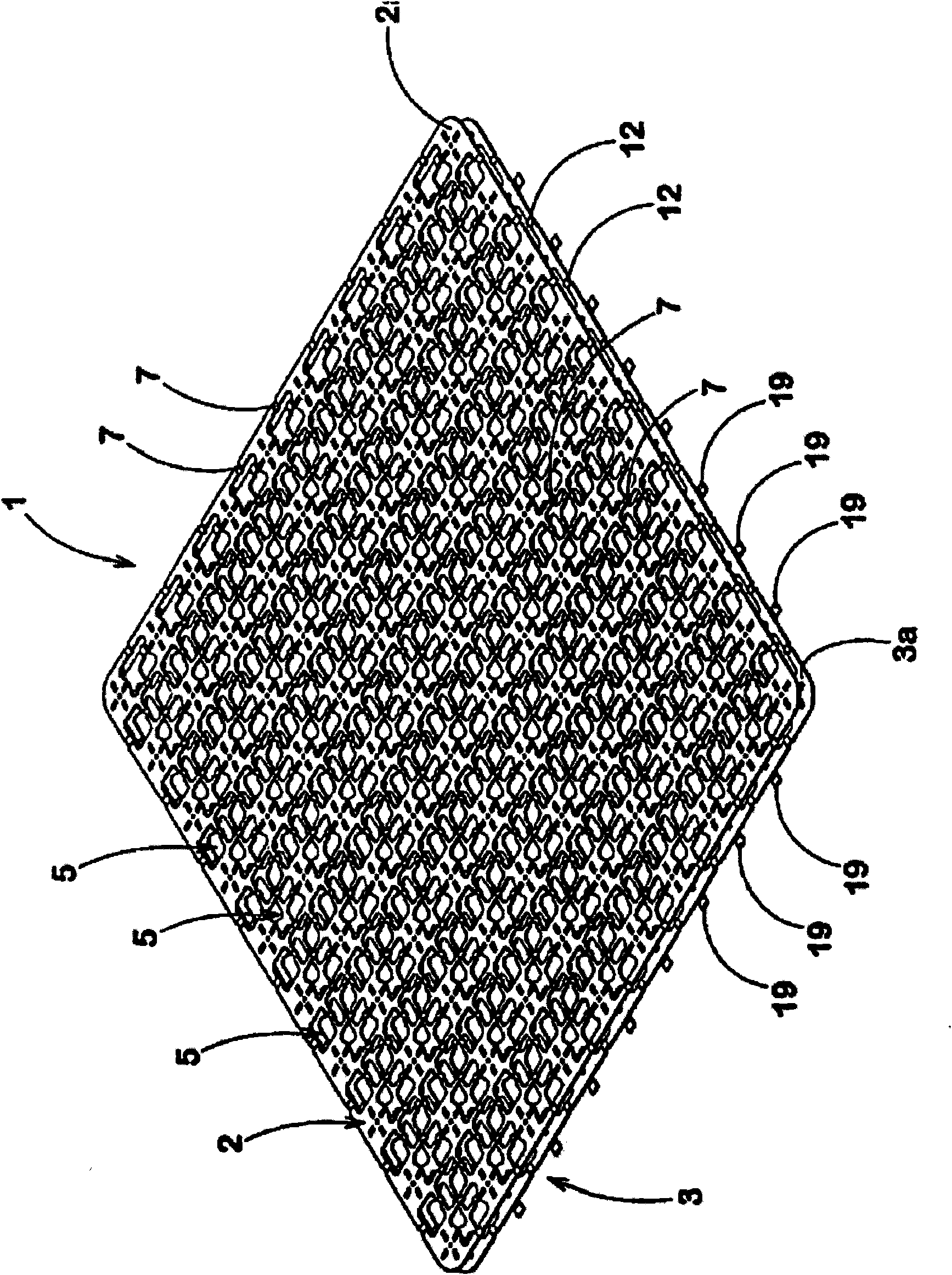
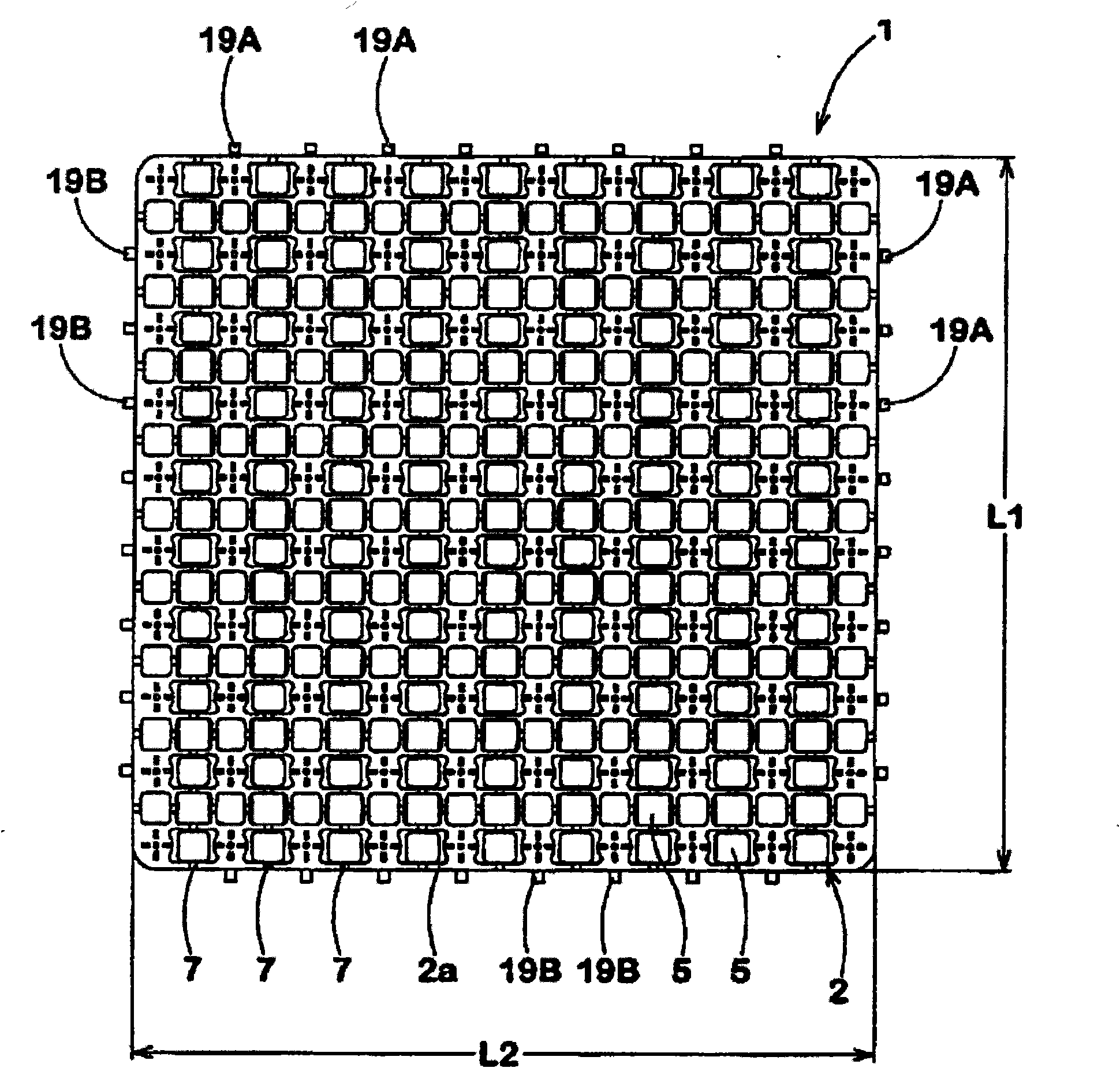
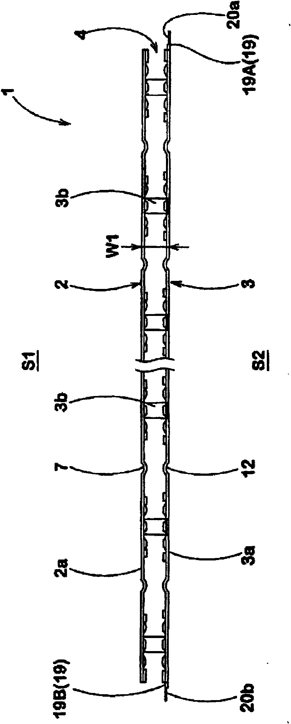
[0072] Please refer to figure 1 , 2 As shown in and 3, the body cooling spacer (hereinafter referred to as "spacer") 1 of the first embodiment of the present invention has an air flow path 4 for air to pass through inside, and can form a vertical length L1 and a horizontal width L2 It is about 400 mm to 500 mm, and the maximum thickness W1 is about 8 mm to 14 mm, which is approximately rectangular in the planar direction and has a small thickness. Furthermore, the spacer 1 can be deformed into a circular or polygonal shape, and its size can also be changed arbitrarily.

[0073] The spacer 1 includes a first piece 2 and a second piece 3, the first piece 2 is formed on the side of the...


PUM


Abstract

The invention relates to a spacing part for cooling a body and an air-conditioner pad using the same, wherein the spacing part for cooling the body is sheet-shaped and comprises a first sheet part and a second sheet part. The first sheet part has a first surface for forming the spacing part. The second sheet part is arranged in opposition to the first sheet part and has a second surface which is opposite to the first surface of the spacing part. The first sheet part comprises a first surface material part which is extended from the first surface and a plurality of first convex parts which are side-protuberant from the first surface material part to the second sheet part; and the second sheet part comprises a second surface material part which is extended from the second surface and a plurality of second convex parts which are side-protuberant from the second surface material part to the first sheet part. The inosculation of the first convex parts and the second convex parts enables the first surface material part and the second surface material part to be supported at intervals and to form an air flow path between the first surface material part and the second surface material part, and a plurality of air holes communicated with the air flow path are formed on a first surface part at least.

Description

technical field [0001] The invention relates to a spacer for body cooling that can maintain the cooling effect and improve the convenience of use and production, and an air-conditioning pad using the spacer. Background technique [0002] Conventional spacers for cooling the body, as shown in Japanese Patent No. 4067034, increase the temperature difference near the body surface by allowing air to pass through the interior, so that the user feels cool. Such a spacer is used, for example, by laying it on a bed or the like, so that the user can obtain a comfortable sleep even at night when it is difficult to fall asleep in summer. [0003] Such as Figure 20a As shown, the existing spacer a includes a surface material part b extending on the first surface, and a plurality of convex parts c protruding from the surface material part b to other sides. The protrusion c is provided with a hole d in order to allow air to pass through the inside of the spacer a. In addition, in order...

Claims


Application Information

Patent Timeline
IPC IPC(8): A47C27/00A47C27/12A47C21/04
Inventor 原岛彻横田慎太郎
Owner ATEX CO LTD
Why Eureka
Try Eureka