Carbon fiber woven fabric for fuel cell gas diffusion layer and fuel cell

A gas diffusion layer, carbon fiber fabric technology, applied in electrical components, battery electrodes, circuits, etc., can solve the problems of uneven absorption thickness, low buffering, and many processes that consume energy, and achieve the effect of high power generation capacity

Active Publication Date: 2020-06-12
NACHI-FUJIKOSHI +1
View PDF12 Cites 0 Cited by
  • Summary
  • Abstract
  • Description
  • Claims
  • Application Information

AI Technical Summary

Problems solved by technology

[0008] Since most of such gas diffusion layers are made of paper, the cushioning ability to absorb uneven thickness is also low, and there are many steps that consume energy, so there is a problem that the production cost is high.

Method used


Image

  • Carbon fiber woven fabric for fuel cell gas diffusion layer and fuel cell
  • Carbon fiber woven fabric for fuel cell gas diffusion layer and fuel cell
  • Carbon fiber woven fabric for fuel cell gas diffusion layer and fuel cell

Examples


Embodiment 1

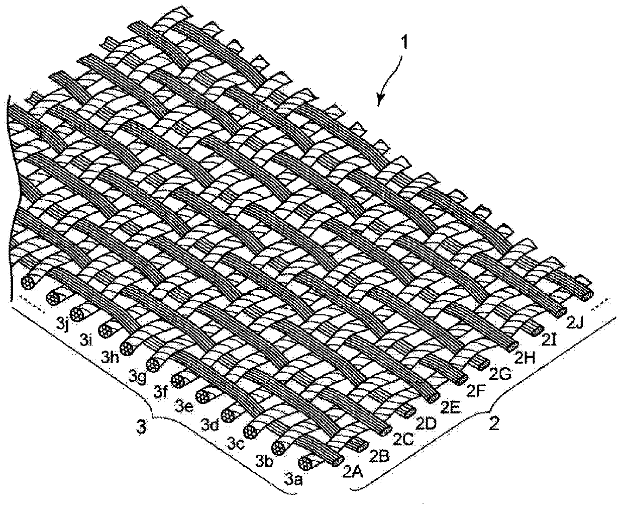
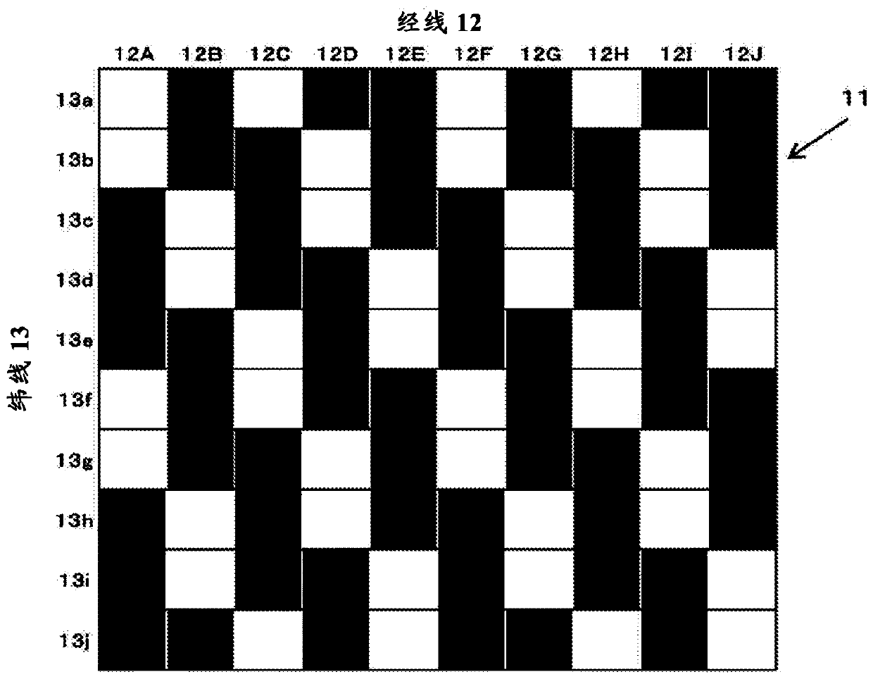
[0082] A fuel cell cell (hereinafter referred to as "cell") was produced using the GDL of each carbon fiber fabric using the material of the present invention and the comparative material, and the power generation performance of the cell was measured, so the measurement results will be described. The GDL used in this measurement was made into the GDL of each carbon fiber fabric which used 2 types of this invention materials (this invention material 1 and 2) and 2 types of comparison materials (comparative materials 1 and 2). Material 1 of the present invention is figure 1 as well as figure 2 In the GDL of the twill weave shown (a weaving method in which one warp passes over three wefts and then passes under two wefts), only the warp is substantially untwisted. In addition, the present invention material 2 is the same as the invention material 1 figure 1 as well as figure 2 In the shown twill-woven GDL, both the warp and the weft are substantially untwisted.

[0083] In c...

Embodiment 2

[0098] Next, in order to compare the ease of fluidity of the fluid (water) in each GDL of the material of the present invention and the comparative material, a water passage test was performed. The GDL used in this test was the present invention material 2 and comparative material 2 (hereinafter referred to as present invention material 3 and comparative material 3) used in Example 1. Figure 12 A schematic plan view of the test setup used in this test is shown in , Figure 13 shown in Figure 12 The X-X profile.

[0099] Regarding this test device, such as Figure 12 as well as Figure 13 As shown, a GDL with a thickness of 0.1 mm x width 50 mm x length 100 mm is set on a steel base and gaskets are placed around it, and the GDL is pressed from above with a transparent resin plate and a steel pressing plate. Airtight. With regard to the hermetic GDL, it is possible to pass such as Figure 13 Check the water flow of the GDL by using the pressing plate with the opening in th...

Embodiment 3

[0102] The difference in the bending amount under predetermined pressing was measured using the inventive material and the comparative material, and the measurement results will be described. In addition, the same invention material and comparative material were also used to measure the same power generation performance as in Example 1, so the measurement results will also be described together.

[0103] The GDL used in the measurement of the amount of bending of the GDL and the measurement of the power generation performance in this example is a material obtained by curing both sides of the material 1 of the present invention used in Example 1 (hereinafter referred to as the present invention). Material 4) and a comparative material obtained by curing both surfaces of Comparative Material 1 used in Example 1 with a thermosetting resin (hereinafter referred to as Comparative Material 4).

[0104] Regarding the curing treatment carried out on both sides of the inventive materia...


PUM


Abstract

This carbon fiber woven fabric for a fuel cell gas diffusion layer makes it possible to reduce thickness if layered inside a fuel cell, and to lower electrical resistance by increasing adhesion when the carbon fiber woven fabric is layered sandwiched between a membrane electrode assembly and a separator. At the same time, this carbon fiber woven fabric for a fuel cell gas diffusion layer has superior diffusing characteristics inside the fuel cell and can generate power efficiently. A carbon fiber woven fabric (1) for a fuel cell gas diffusion layer is formed by the interweaving of a warp (2) and a weft (3), and the threads of the warp (2) or the weft (3) are substantially non-twisted threads. Furthermore, on one surface of the carbon fiber woven fabric (1) for a fuel cell gas diffusion layer, the number of the non-twisted threads, of the warp (2) or the weft (3) non-twisted threads which are interweaved, which lay above the other thread (warp or weft) is greater than the number of thenon-twisted threads of the other thread which lays below.

Description

technical field [0001] The present invention relates to a carbon fiber fabric used as a fuel cell gas diffusion layer (sheet) mounted on vehicles, ships, airplanes, and other transportation devices, and to a fuel cell unit embedded with the carbon fiber fabric as a gas diffusion layer. Background technique [0002] In the past, due to the high concern for environmental issues, the use of fuel cells as new energy sources has attracted attention. Among them, solid polymer fuel cells for households and vehicles (hereinafter referred to as "fuel cells") as the mainstream have the following structure: The membrane electrode assembly (MEA: Membrane Electrode Assembly) that connects the electrode catalyst layer on both sides of the polymer membrane, the gas diffusion layer (GDL: Gas Diffusion Layer) that guides the fuel gas or oxidant gas to the electrode reaction area, and the gas diffusion layer with gas A unit assembly (hereinafter referred to as "fuel cell") consisting of separ...

Claims


Application Information

Patent Timeline
IPC IPC(8): H01M4/96
CPCH01M4/96
Inventor 吉野一郎永井久司熊谷昌信高木顺犬山久夫
Owner NACHI-FUJIKOSHI
Why Eureka
Try Eureka