Battery Cooling Structure

A battery and structure technology, which is applied to the arrangement of secondary batteries, power unit cooling combined, battery temperature control, etc. , Prevent dumping, and achieve the effect of the number of parts

Active Publication Date: 2015-09-02
HONDA MOTOR CO LTD
View PDF5 Cites 0 Cited by
  • Summary
  • Abstract
  • Description
  • Claims
  • Application Information

AI Technical Summary

Problems solved by technology

[0006] However, in the invention described in the aforementioned Patent Document 1, in order to prevent the lower battery module from collapsing due to the weight of the upper battery module, a plurality of pillars for reinforcement are provided on the side surface of the battery case of the lower battery module (see Figure 7 as well as Figure 11 ), due to the part of the column, there is a corresponding problem that the number of parts increases and the structure is complicated
Moreover, since the cooling air flows through the cooling passage formed inside the battery case, when the outside air is used as the cooling air, it may cause contamination of the battery cells housed in the battery case.

Method used


Image

  • Battery Cooling Structure
  • Battery Cooling Structure
  • Battery Cooling Structure

Examples


no. 1 Embodiment approach

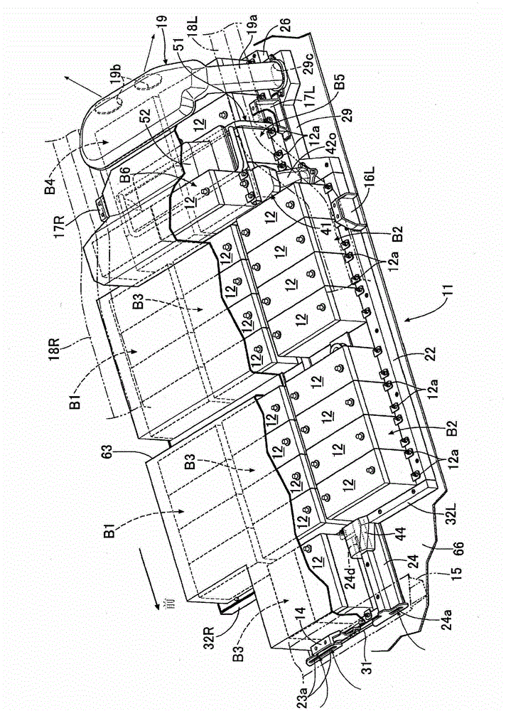
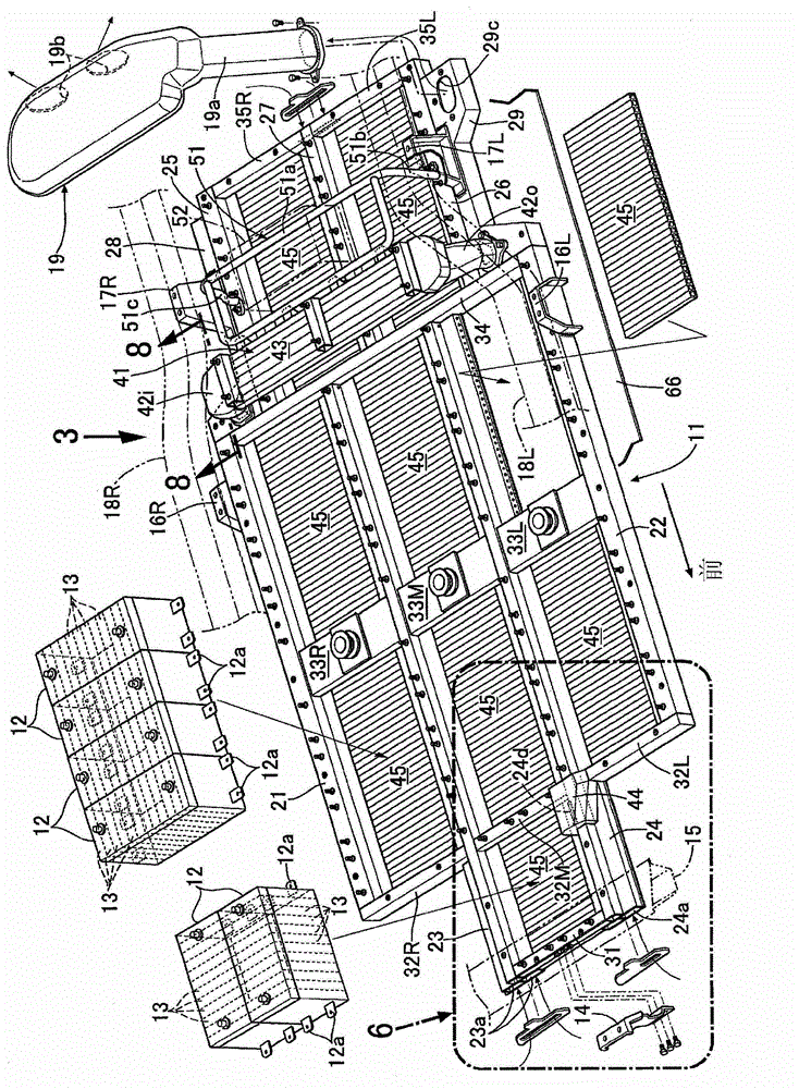
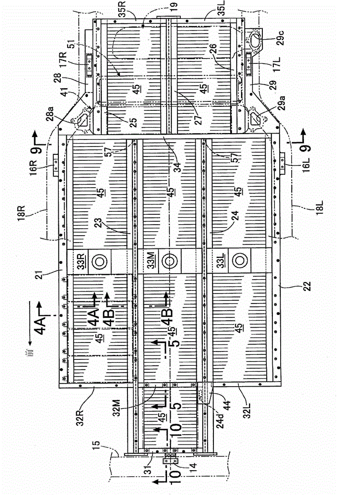
[0052] Such as Figure 1 ~ Figure 3 As shown, the battery unit that supplies electric power to a motor / generator serving as a driving power source of an electric vehicle includes: a plate-shaped tray 11; The shape of each battery module 12 is a rectangular parallelepiped, and a plurality of battery cells 13 electrically connected in series are accommodated therein. figure 2 ). Two brackets 12 a , 12 a protrude from both ends of the battery module 12 in the longitudinal direction. The brackets 12 a , 12 a are used to fix the battery module 12 to the tray 11 .

[0053]The mounting bracket 14 provided at the front of the panel 11 is coupled to the cross member 15 of the vehicle body, and the two mounting brackets 16L, 17L provided at the left rear of the panel 11 are coupled to the side frame 18L on the left side. Two mounting brackets 16R, 17R provided at the right rear portion of 11 are coupled to a right side frame 18R, whereby the battery unit is suspended and supported by...


PUM


Abstract

A battery cooling structure is provided in which since a battery support member (43) that is disposed above a lower layer battery group (B4, B5) and supports an upper layer battery group (B6) on its upper face is formed so as to be hollow, and the upper layer battery group (B6) is cooled by a cooling medium that flows in an interior of the battery support member (43), due to the battery support member (43) having the dual function of supporting the upper layer battery group (B6) and cooling the upper layer battery group (B6), it is possible to cut the number of components and simplify the structure. Moreover, since the cooling medium flows in the interior of the battery support member (43) and does not come into direct contact with the upper layer battery group (B6), the upper layer battery group (B6) is not contaminated by the cooling medium.

Description

technical field [0001] The present invention relates to a method for arranging a battery supporting member above a lower battery stack, supporting an upper battery stack on the upper surface of the battery supporting member, and cooling the batteries of the lower battery stack and the upper battery stack by circulation of a refrigerant structure. Background technique [0002] The battery modules containing multiple battery cells inside the module case are stacked in upper and lower layers, and the air sucked by the blower is circulated from the intake port at one end of the upper and lower module cases to the exhaust port at the other end. Thus, a technique for realizing cooling of a battery module is known from Patent Document 1 below. [0003] prior art literature [0004] patent documents [0005] Patent Document 1: Japanese Patent Laid-Open No. 2010-15931 [0006] However, in the invention described in Patent Document 1, in order to prevent the lower battery module f...

Claims


Application Information

Patent Timeline
Patent Type & Authority Patents(China)
IPC IPC(8): H01M10/613H01M10/6568H01M10/6556B60K1/04B60K11/06H01M2/10H01M50/209H01M50/244H01M50/249
CPCH01M2/1077H01M10/6563H01M10/613H01M10/647H01M10/5016H01M10/625Y02E60/10H01M50/249H01M50/209H01M50/244H01M10/60
Inventor 藤井辽山本康一片山吾一
Owner HONDA MOTOR CO LTD
Why Eureka
Try Eureka