Overhead travelling carriage system

a travelling carriage and overhead buffer technology, applied in the direction of conveyor parts, transportation and packaging, railway components, etc., can solve the problem of not having enough space to provide the overhead buffer between the load ports, and achieve the effect of effectively utilizing the space located below the overhead buffer, convenient transfer, and convenient attachment to the running rail

Active Publication Date: 2008-10-28
MURATA MASCH LTD
View PDF26 Cites 38 Cited by
  • Summary
  • Abstract
  • Description
  • Claims
  • Application Information

AI Technical Summary

Benefits of technology

[0004]It is an object of the aspect of the present invention in Claim 2 to allow an article to be easily transferred between the load port and the overhead buffer. Another object of this aspect is to use a mechanism for controlling stopping at the load port to control stopping at the overhead buffer.
[0005]It is an object of the aspect of the present invention in Claim 3 to allow the article to be easily transferred between the overhead travelling carriage and the overhead buffer.
[0012]In the overhead travelling carriage system according to the present invention, the overhead buffer is provided on a side of the running rail, for example, opposite the processing device with respect to the running rail. Accordingly, the overhead buffer can be installed even if the load ports are consecutively arranged in the processing device, so that there is no space between the load ports and below the running rail. This allows the overhead buffer to be efficiently provided close to the load port. Further, the overhead buffer can be provided at a higher position than when it is provided below the running rail and between the load ports. It is thus possible to effectively utilize a space located below the overhead buffer. The overhead travelling carriage is provided with the means for laterally moving the platform toward the overhead buffer. The overhead buffer supports the article below the bottom surface of the article placed on the running overhead travelling carriage. Accordingly, when the platform is laterally moved toward the overhead buffer and is then lowered, the article can be transferred between the overhead buffer and the platform. Thus, the lateral movement of the platform is combined with its elevation and lowering and further with the running of the overhead travelling carriage if required to enable the article to be transferred between the overhead buffer and the load port.
[0013]According to the aspect of the present invention in Claim 2, the overhead buffer is placed so as to transfer the article to and from the overhead travelling carriage, at almost the same position as that of the load port in the running direction of the running rail. For example, the overhead buffer is placed opposite the load port. Thus, for example, a dog (mark) for controlling the stopping of the overhead travelling carriage at the load port can be used to control the stopping of the overhead travelling carriage at the overhead buffer. This allows the dog to be easily attached to the running rail or the like. Further, for the transfer between the overhead buffer and the load port, the overhead travelling carriage need not be run, or even if it is run, it has only to run a short distance. This facilitates the transfer between the overhead buffer and the load port.

Problems solved by technology

However, if load ports are consecutively arranged, there is no space enough to provide the overhead buffer between the load ports.

Method used


Image

  • Overhead travelling carriage system
  • Overhead travelling carriage system
  • Overhead travelling carriage system

Examples


Embodiment Construction

[0023]An optimum embodiment will be shown below which implements the present invention.

[0024]FIGS. 1 to 6 show an embodiment.

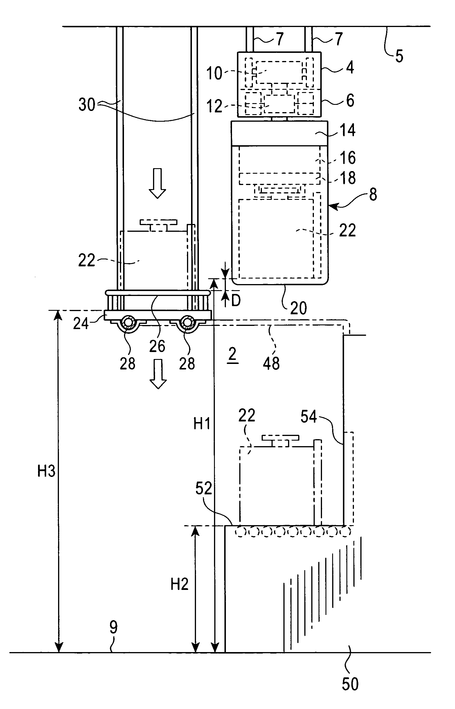
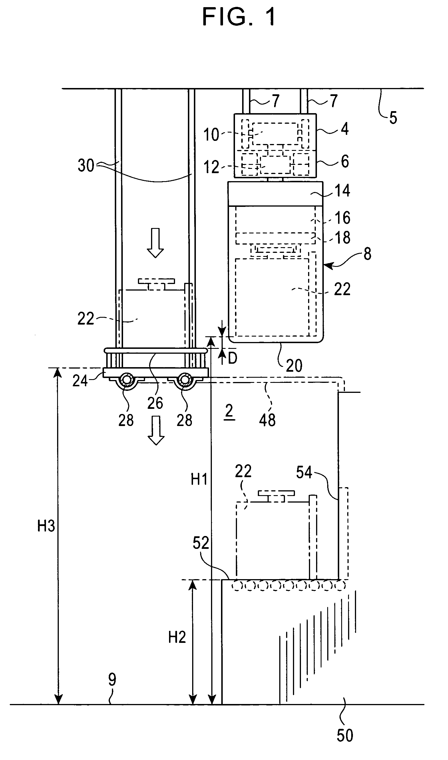
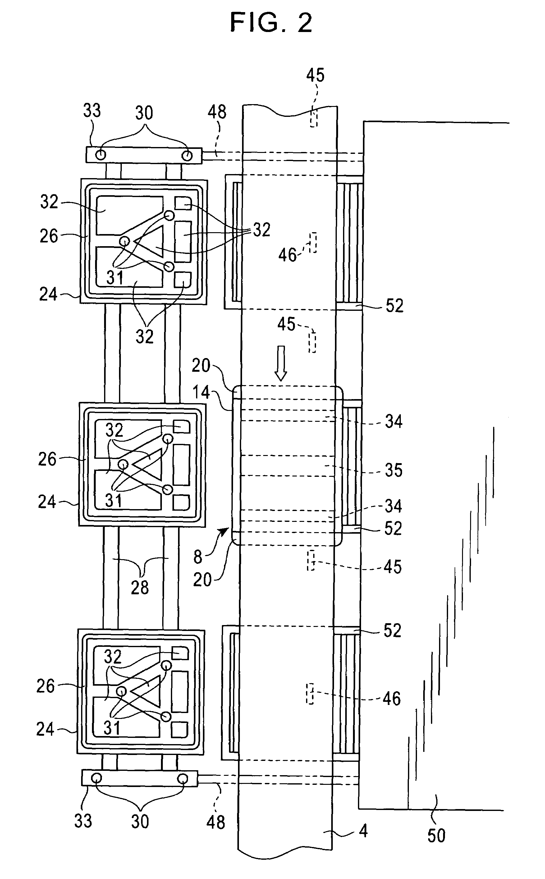
[0025]2 is an overhead travelling carriage system installed in a clean room or the like. 4 is a running rail hung from a ceiling 5 in a supportive manner using hanging bolts 7. An electricity feeding rail 6 is mounted on a bottom surface of the running rail 4. An overhead travelling carriage 8 comprises a running driving section 10 that runs through the running rail 4 and a non-contact electricity feeding section 12 that receives electricity fed through the electricity feeding rail 6 by means of, for example, non-contact electricity feeding. The electricity feeding rail 6 is provided with, for example, a communication line used between the overhead travelling carriage 8 and a controller (not shown in the drawings) and a dog for controlling stopping at a load port. The non-contact electricity feeding section 12 is provided not only with a coil for non-contact e...


PUM


Abstract

An overhead buffer 24 is provided on a side of a running rail 4 for an overhead travelling carriage 8. The height level of an article on the overhead buffer 24 is slightly lower than that on the running overhead travelling carriage 8. This height is at least such that the overhead buffer 24 does not interfere with an operator. According to the present invention, the overhead buffer can be installed even if load ports are consecutively provided.

Description

FIELD OF THE INVENTION[0001]The present invention relates to an overhead travelling carriage system, and in particular, to an overhead buffer for temporarily storing an article.BACKGROUND OF THE INVENTION[0002]In an overhead travelling carriage system, an article is conveyed by running an overhead travelling carriage along a running rail installed close to a ceiling in a clean room or the like. An overhead buffer can be effectively installed close to a load port (a ground workstation provided in a processing device or the like) in order to increase the efficiency of the overhead travelling carriage system. The Japanese Patent No. 3067656 proposes provision of an overhead buffer between load ports and below the running rail. However, if load ports are consecutively arranged, there is no space enough to provide the overhead buffer between the load ports.SUMMARY OF THE INVENTION[0003]It is an object of the present invention to provide an overhead travelling carriage system that allows ...

Claims


Application Information

Patent Timeline
Patent Type & Authority Patents(United States)
IPC IPC(8): H01L21/677B65G1/00B61D27/00B65G1/04B66C11/06B66C15/00B66C15/04B66C17/00
CPCB65G1/0457H01L21/67769H01L21/67766Y10S414/14B66C17/00B66C15/04B66C15/00
Inventor NAKAO, TAKASHITANAKA, MAKOTO
Owner MURATA MASCH LTD
Why Eureka
Try Eureka