
Conductive heat transfer for electrical devices from the solder side and component side of a circuit card assembly

a circuit card and component technology, applied in the direction of electrical apparatus contruction details, semiconductor/solid-state device details, lighting and heating apparatus, etc., can solve the problems of component temperature exceeding the temperature rating, not obtaining cooling effect, adding cost, etc., and achieve the effect of reducing the component temperature and below the thermal limi

Inactive Publication Date: 2008-10-28
FUJITSU LTD
View PDF11 Cites 4 Cited by
  • Summary
  • Abstract
  • Description
  • Claims
  • Application Information

AI Technical Summary

Benefits of technology

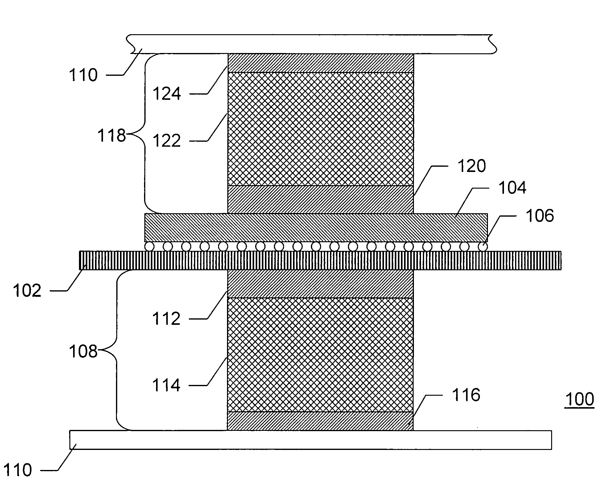
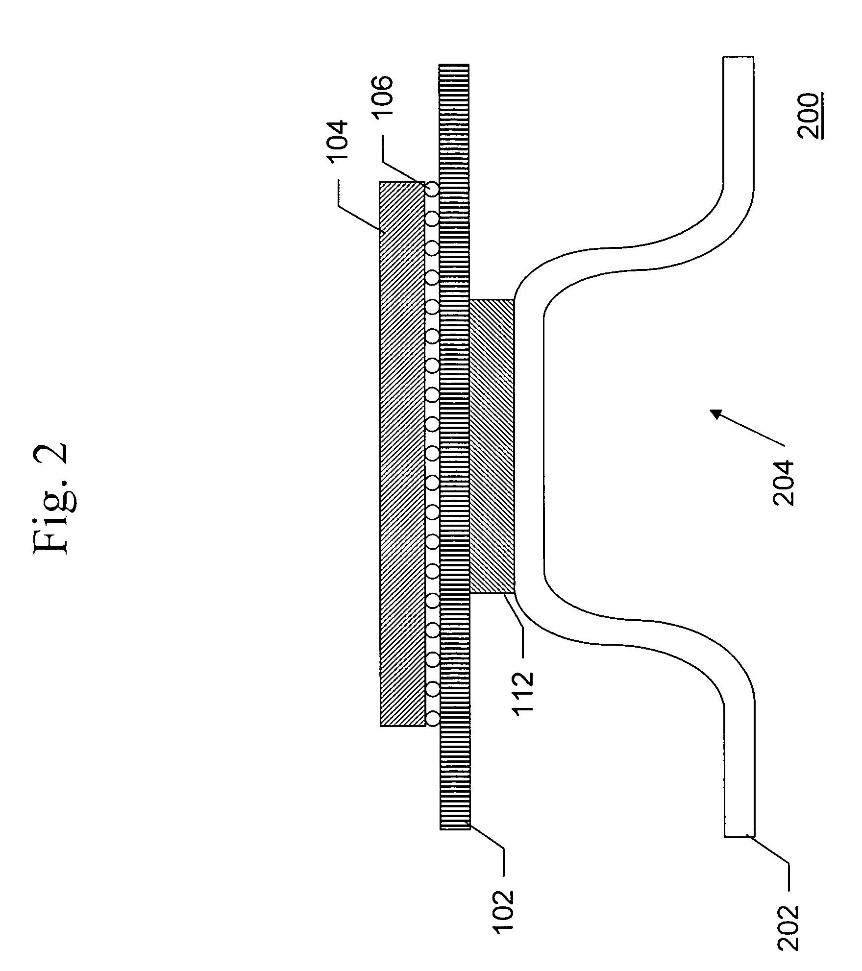
This patent describes a new way to cool down electronic components, like ball grid array packages, to prevent them from overheating. The approach involves using the backside of the printed circuit board, which has a lot of copper coverage, as a heat conduit to remove heat from the component. A compliant material is placed on the backside of the circuit board to make direct contact with the component, and an optional aluminum block is added to improve heat transfer. The compliant material can be applied over small surface mount components like capacitors and resistors. The invention also includes a thermally conductive member that can be in contact with the circuit board or an enclosure to further facilitate heat transfer. A fan can be added for added cooling power. Overall, this invention helps to keep electronic components cool and within their safe operating limits.

Problems solved by technology

The amount of heat generated by the electrical components within a small enclosure can cause the components to exceed their temperature rating, especially when relying on convection and radiation heat transfer to dissipate the heat
However, they do not obtain the cooling effect that a good conductive path would provide.
A fan can improve the convective cooling but it also adds cost and decreases the reliability and service life of the system since fans have a low operating life.

Method used


Image

  • Conductive heat transfer for electrical devices from the solder side and component side of a circuit card assembly
  • Conductive heat transfer for electrical devices from the solder side and component side of a circuit card assembly
  • Conductive heat transfer for electrical devices from the solder side and component side of a circuit card assembly

Examples


Embodiment Construction

[0017]The present invention employs the backside of the printed circuit board to remove heat from an electrical component. Technology today dictates that electrical components are capable of higher power dissipations. Typically, these high power components are a ball grid array package. Since the package has many solder balls and the printed circuit board (PCB) below it has a large percentage of copper coverage, the circuit board becomes a good conductive heat path. The backside of the PCB is available for heat removal.

[0018]This invention mounts a compliant thermal interface material on the backside of the PCB directly below a high heat dissipating electrical device. The compliant material can be placed directly over small surface mount capacitors and resistors. An optional aluminum block is adhered to the top of the thermal interface material. The opposite face of the optional aluminum block mates to the enclosure. To insure there is no air at the interface between the optional al...


PUM


Abstract

An apparatus for conductive heat transfer for electrical devices from the solder side of a circuit card assembly can significantly reduce the component temperature, thereby maintaining the electrical device below its thermal limit. The apparatus comprises a thermally conductive member mountable on an opposite face of a circuit board from a face of the circuit board on which an electrical component is mounted, the thermally conductive member operable to conduct heat generated by the electrical component away from the electrical component.

Description

BACKGROUND OF THE INVENTION[0001]1. Field of the Invention[0002]The present invention relates to an apparatus for conductive heat transfer for electrical devices from the solder side of a circuit card assembly.[0003]2. Description of the Related Art[0004]The trend in electrical components has been towards faster and more integrated components in smaller enclosures. As more, higher speed, circuitry is included in electrical components, the components tend to use more power and, therefore, dissipate more heat. The amount of heat generated by the electrical components within a small enclosure can cause the components to exceed their temperature rating, especially when relying on convection and radiation heat transfer to dissipate the heat[0005]Heatsinks and other traditional electrical component cooling devices are mounted to the top of a component. They can improve the component's convection and radiation heat transfer. However, they do not obtain the cooling effect that a good conduc...

Claims


Application Information

Patent Timeline
Patent Type & Authority Patents(United States)
IPC IPC(8): H05K7/20F28F7/00
CPCH01L23/367H01L23/433H05K1/0206H01L2224/16H05K2201/066H05K2201/10734H01L2924/00014H01L2924/00011H01L2224/0401
Inventor PEDOEEM, ALBERTYUAN, LANGBRAUN, WILLIE
Owner FUJITSU LTD
Learn More