Oscillating ball throwing machine

a ball throwing machine and oscillating technology, applied in the field of ball throwing machines, can solve the problems of difficult implementation and accurate control of electronic motor controls, high manufacturing cost, and high cost for consumers

Active Publication Date: 2008-11-04
TH LOBSTER TENNIS LLC
View PDF25 Cites 25 Cited by
  • Summary
  • Abstract
  • Description
  • Claims
  • Application Information

AI Technical Summary

Problems solved by technology

Typically, however, this is achieved through complicated electronic circuitry and / or complicated mechanical components.
Although these improved throwing direction variations are desirable for more realistic practice, the construction of these devices often makes them expensive to manufacture and therefore expensive for the consumer.
In addition, providing electronic motor controls can be difficult to implement and accurately control.

Method used


Image

  • Oscillating ball throwing machine
  • Oscillating ball throwing machine
  • Oscillating ball throwing machine

Examples


Embodiment Construction

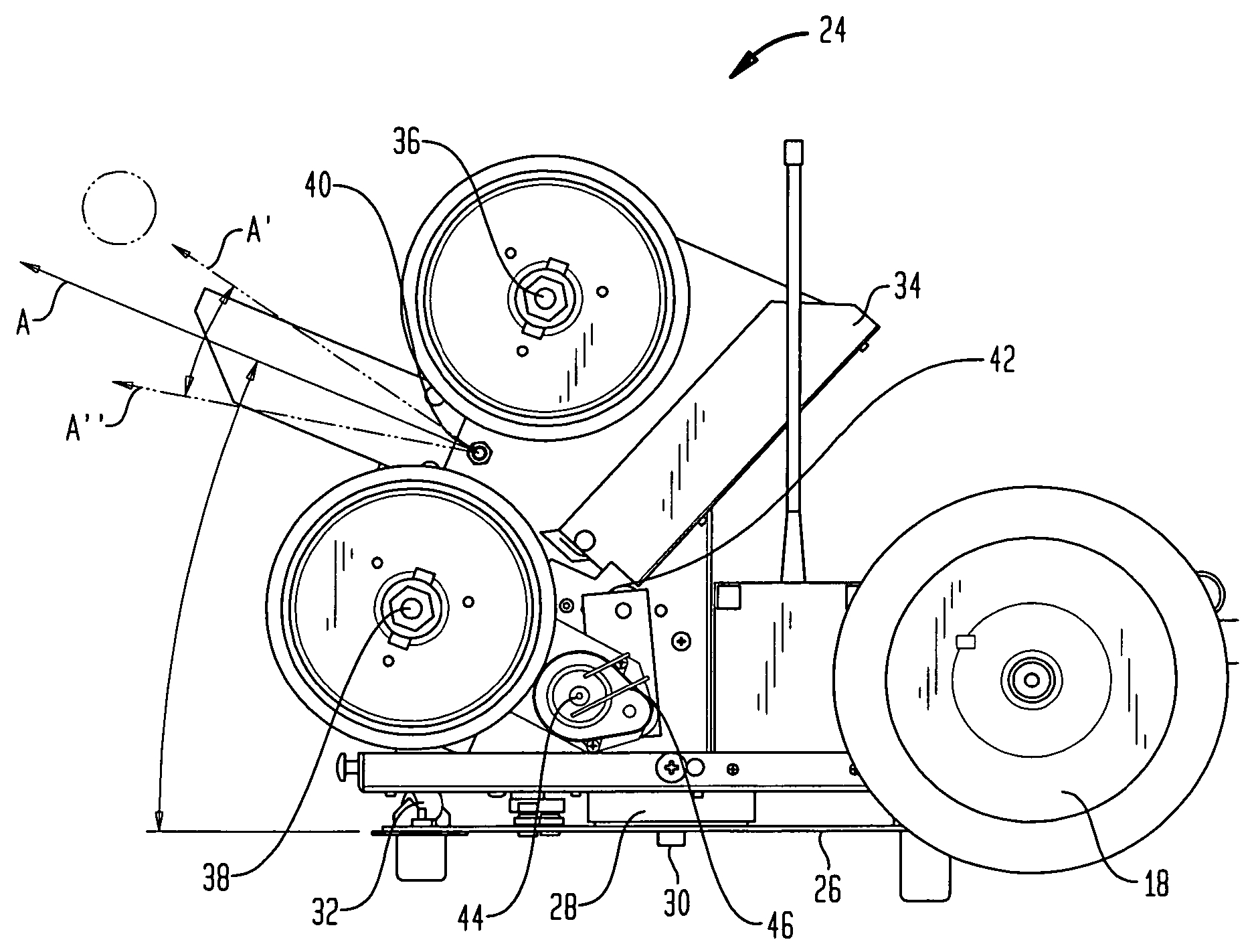
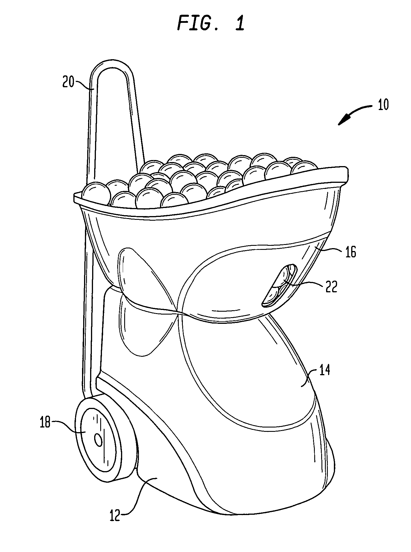
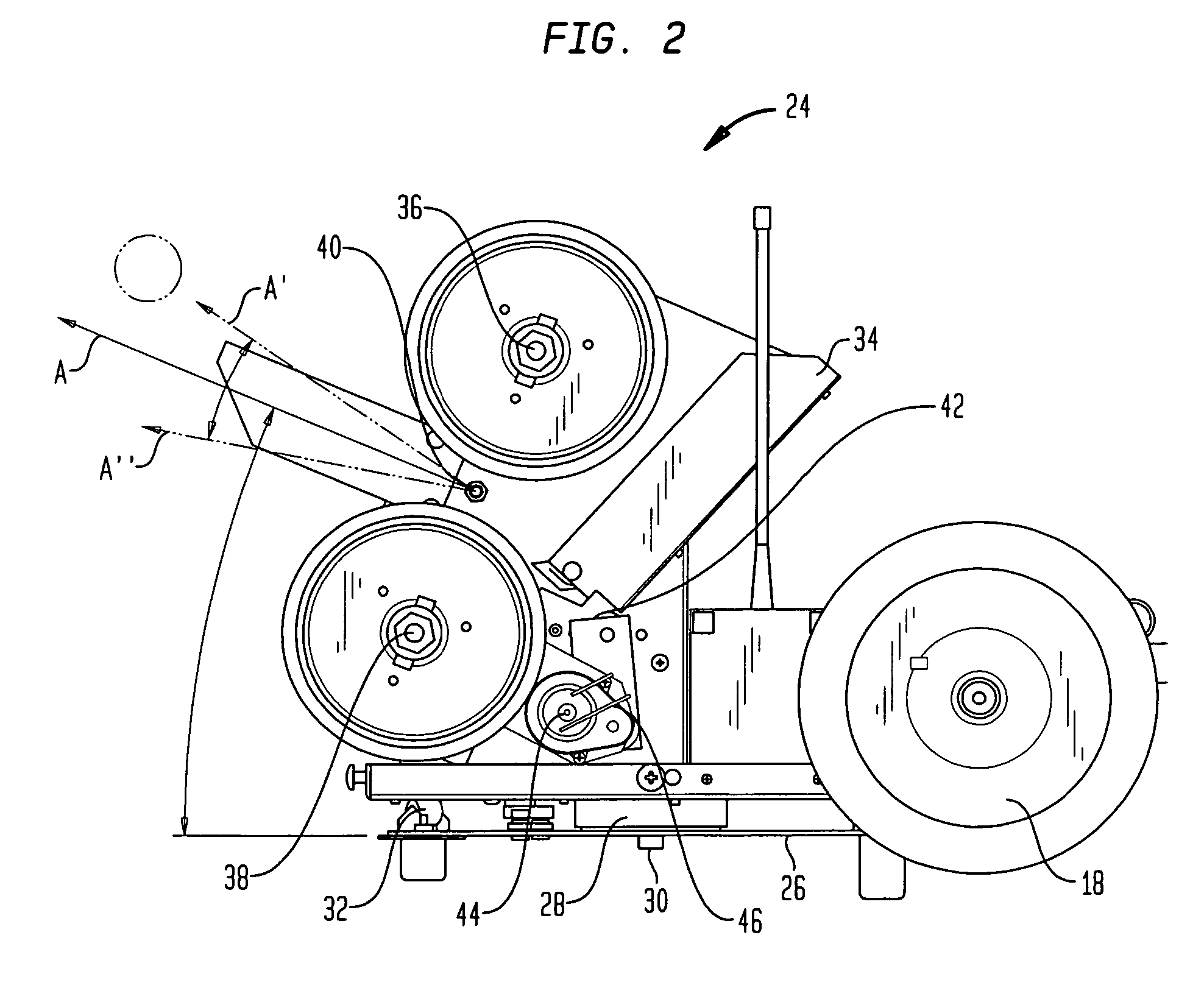
[0020]Referring to the drawings, wherein like reference numerals represent like elements, there is shown in FIG. 1, in accordance with one preferred embodiment of the present invention, a ball throwing machine, generally designated by reference numeral 10. As will be discussed further below, the improved ball throwing machine 10 of the present invention allows for the setting of a nominal vertical throwing adjustment, as well as fine oscillation adjustments with respect to this nominal throwing angle. In accordance with the present invention, machine 10 preferably utilizes a motor assembly in conjunction with a linkage or cam assembly to achieve this operation, as will be described in more detail below.

[0021]Ball throwing machine 10, in the example depicted in the figures, is designed to throw tennis balls and preferably includes a main housing 12, which holds and protects the majority of the mechanical and / or electrical components of the machine, a projection opening 14 formed in h...


PUM


Abstract

A ball throwing machine for throwing projectiles, such as tennis balls or baseballs, includes a yoke assembly for projecting balls and a motor assembly for providing both nominal vertical throwing as well as oscillating vertical movement of the yoke assembly. The machine provides fine variations in the vertical trajectories of the balls being thrown and preferably eliminates the need for complicated electronic circuit controls and / or mechanical components.

Description

CROSS-REFERENCE TO RELATED APPLICATIONS[0001]This application claims the benefit of the filing date of U.S. Provisional Patent Application No. 60 / 633,128 filed Dec. 3, 2004, the disclosure of which is hereby incorporated herein by reference.BACKGROUND OF THE INVENTION[0002]The present invention relates to ball throwing machines, and more particularly, to ball throwing machines that allow for both variations in throwing distance, as well as in throwing direction.[0003]Many athletes utilize ball throwing or projecting machines to practice their particular sport. For example, tennis ball throwing machines are extremely useful practice tools for tennis players. Typically, these machines are loaded with tennis balls and placed at an end of a tennis court which is opposite from the practicing player. The desired trajectory of the ball is usually set, either manually by the player or with the aid of a remote control. Balls are then lobbed or shot out of the machine towards the player, to a...

Claims


Application Information

Patent Timeline
Patent Type & Authority Patents(United States)
IPC IPC(8): F41B4/00
CPCA63B69/406
Inventor SMITH, PHILIP
Owner TH LOBSTER TENNIS LLC
Why Eureka
Try Eureka