Arrangement and method for the generation of EUV radiation of high average output

a technology of euv radiation and high average output, which is applied in the field of arrangement and a method for the generation of euv radiation of high average output, can solve the problems of reducing the radiation output in the euv range of filters of this kind, and mirrors that require rotary mirror drives with so as to achieve the effect of not requiring extremely high rotational speeds of mechanical components

Inactive Publication Date: 2007-08-09
XTREME TECH
View PDF5 Cites 49 Cited by
  • Summary
  • Abstract
  • Description
  • Claims
  • Application Information

AI Technical Summary

Benefits of technology

[0015]It is the primary object of the invention to find a novel possibility for generating EUV radiation of high average output which permits a time-multiplexing of the radiat

Problems solved by technology

However, as a result of findings of recent feasibility studies, the requirements for an EUV radiation source suitable for production lines in semiconductor lithography have been raised considerably in connection with the following principal points:1. It is known that the reflectivity of reflection optics with grazing incidence (grazing incidence optics) decreases considerably as the angle of incidence increases (relative to the mirror surface) and, therefore, the collection efficiency does not scale linearly with the collecting solid angle.
However, filters of this kind also reduce the radiation output in the EUV range (L. Smaenok, EUVL Sympos

Method used


Image

  • Arrangement and method for the generation of EUV radiation of high average output
  • Arrangement and method for the generation of EUV radiation of high average output
  • Arrangement and method for the generation of EUV radiation of high average output

Examples


Embodiment Construction

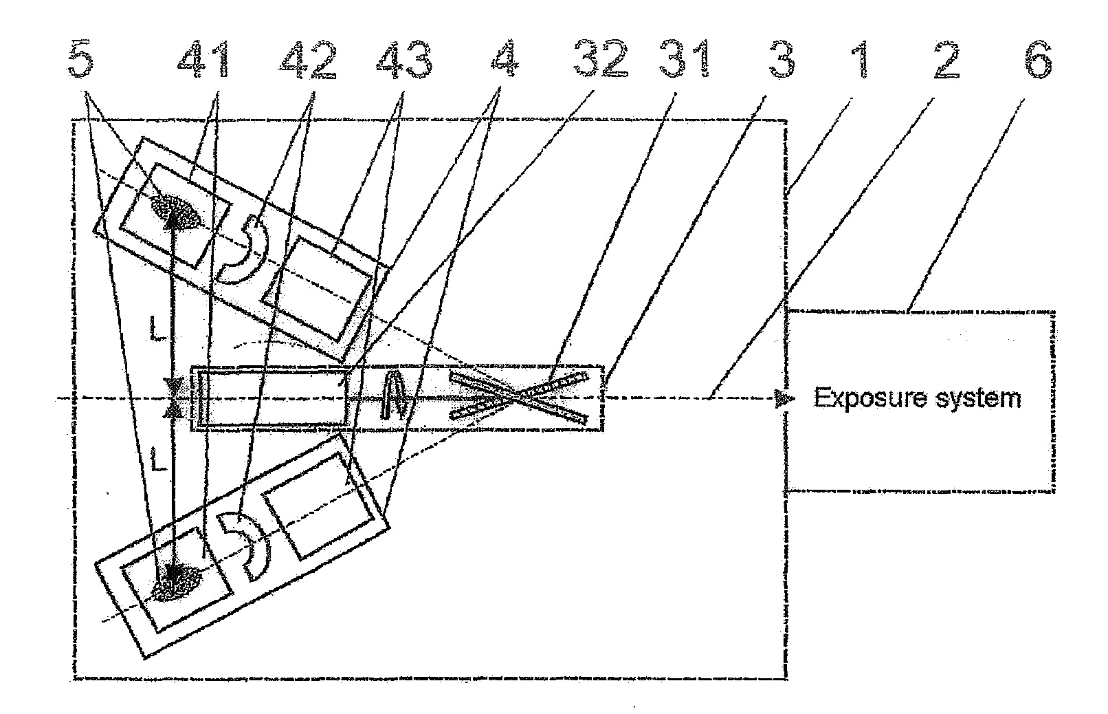
[0042]In a basic variant, as is shown in FIG. 1, the arrangement according to the invention has a plurality of (in this case, two) source modules 4 which generate EUV radiation independently in each case in any conventional manner (Z-pinch, hollow-cathode triggered pinch or plasma focus arrangements). The use of a discharge arrangement with rotating electrodes as is known, e.g., from EP 1 401 248 is advantageous for the life of the EUV source. Further, the arrangement contains within a vacuum chamber 1 a reflector arrangement 3 which comprises a rotary mirror 31 and a drive unit 32 and which couples in the beam bundles of all of the source modules 4 successively in a stepwise manner on an optical axis 2 in direction of the exposure system 6 after an entire sequence of pulses 45 of each of the source modules 4 has been coupled in.

[0043]Each of these source modules 4 by itself is capable of operating at a pulse repetition frequency of >12 kHz for purposes of an acceptable thermal load...


PUM


Abstract

The invention is directed to an arrangement and a method for the generation of EUV radiation of high average output, preferably for the wavelength region of 13.5 nm for use in semiconductor lithography. It is the object of the invention to find a novel possibility for generating EUV radiation of high average output which permits a time-multiplexing of the radiation of a plurality of source modules in a simple manner without overloading the source modules and without requiring extremely high rotational speeds of optical-mechanical components. This object is met, according to the invention, in that a plurality of identically constructed source modules which are arranged so as to be distributed around a common optical axis are directed to a rotatably mounted reflector arrangement which successively couples in the beam bundles of the source modules along the optical axis. The reflector arrangement has a drive unit by which a reflecting optical element is adjustable so as to be stopped temporarily in angular positions that are defined for the source modules and is oriented to the next source module in intervals between two exposure fields of a wafer by means of control signals emitted by an exposure system.

Description

CROSS-REFERENCE TO RELATED APPLICATION[0001]This application claims priority German Application No. 10 2006 003 683.2, filed Jan. 24, 2006, the complete disclosure of which is hereby incorporated by reference.BACKGROUND OF THE INVENTION[0002]1. a) Field of the Invention[0003]The invention is directed to an arrangement and a method for the generation of EUV radiation of high average output for the lithographic exposure of wafers, wherein a plurality of identically constructed source modules which are distributed in a vacuum chamber around an optical axis of the vacuum chamber are triggered successively for generating beam bundles from plasma emitting EUV radiation in order to couple in their beam bundles in direction of the common optical is by means of a reflector arrangement which is mounted so as to be rotatable. The invention is applied in radiation sources for semiconductor lithography, preferably for the wavelength region of 13.5 nm.[0004]2. b) Description of the Related Art[00...

Claims


Application Information

Patent Timeline
IPC IPC(8): G01J3/10
CPCB82Y10/00G01J1/04G01J1/0414G01J1/08G03F7/70208G03F7/70041G03F7/7005G03F7/70166G03F7/70033
Inventor KLEINSCHMIDT, JUERGEN
Owner XTREME TECH
Why Eureka
Try Eureka