Flexible display apparatus having roller that rotates by unfolding operation-force of user

a flexible display and operation force technology, applied in the direction of electrical apparatus casings/cabinets/drawers, identification means, instruments, etc., can solve the problems of no appropriate suggestion, no suitable solution, and difficult to apply the spiral spring to the flexible display, so as to prolong the battery consumption time, save packaging space, and reduce cost and weight

Active Publication Date: 2017-03-02
LIM YOUSEOB
View PDF10 Cites 52 Cited by
  • Summary
  • Abstract
  • Description
  • Claims
  • Application Information

AI Technical Summary

Benefits of technology

[0009]According to the present invention, the flexible display apparatus to which the operating force converter is applied can drive the roller A or the roller B by means of the operating force converter upon the unfolding operation of the user, without having any motor, components related to the motor, and a motor controller, thereby giving some advantages such as packaging space saving, cost and weight reduction through the decrement of the number of components, and the extension of battery consumption time.
[0010]In addition, the flexible display apparatus according to the present invention can mechanically convert the unfolding or folding operating force linearly applied by the user into the rotational force of the roller by means of the operating force converter, without having any spiral spring, thereby removing the rotational force reduction caused by the prescription function loss of the spiral spring and also giving some advantages such as the easiness of packaging space occupation and the weight reduction effects obtained by the nonexistence of the spiral spring.
[0011]Further, the flexible display apparatus according to the present invention can allow the operating force converter to be mechanically synchronized with the user's unfolding speed to control the rotational speed of the roller, thereby preventing the flexible display panel A or the flexible display panel B from being torn out or damaged due to the excessive rotation of the roller A or the roller B and also preventing the flexible display panel A or the flexible display panel B from being deflected due to the insufficient rotation of the roller A or the roller B.

Problems solved by technology

In this case, it is hard to apply the motor to the flexible display because of the miniaturization trend of the flexible display and the limitation in the battery capacity, and it is also hard to apply the spiral spring to the flexible display because of the prescription function loss of the spiral spring, the difficulty in the occupation of space, and the problem of the control in rotational force.
Up to now, however, there is no appropriate suggestion capable of solving the above-mentioned problems, and accordingly, there is a definite need for the development of a new method for generating the rotational force of the roller, not through the motor or spiral spring.

Method used


Image

  • Flexible display apparatus having roller that rotates by unfolding operation-force of user
  • Flexible display apparatus having roller that rotates by unfolding operation-force of user
  • Flexible display apparatus having roller that rotates by unfolding operation-force of user

Examples


first embodiment

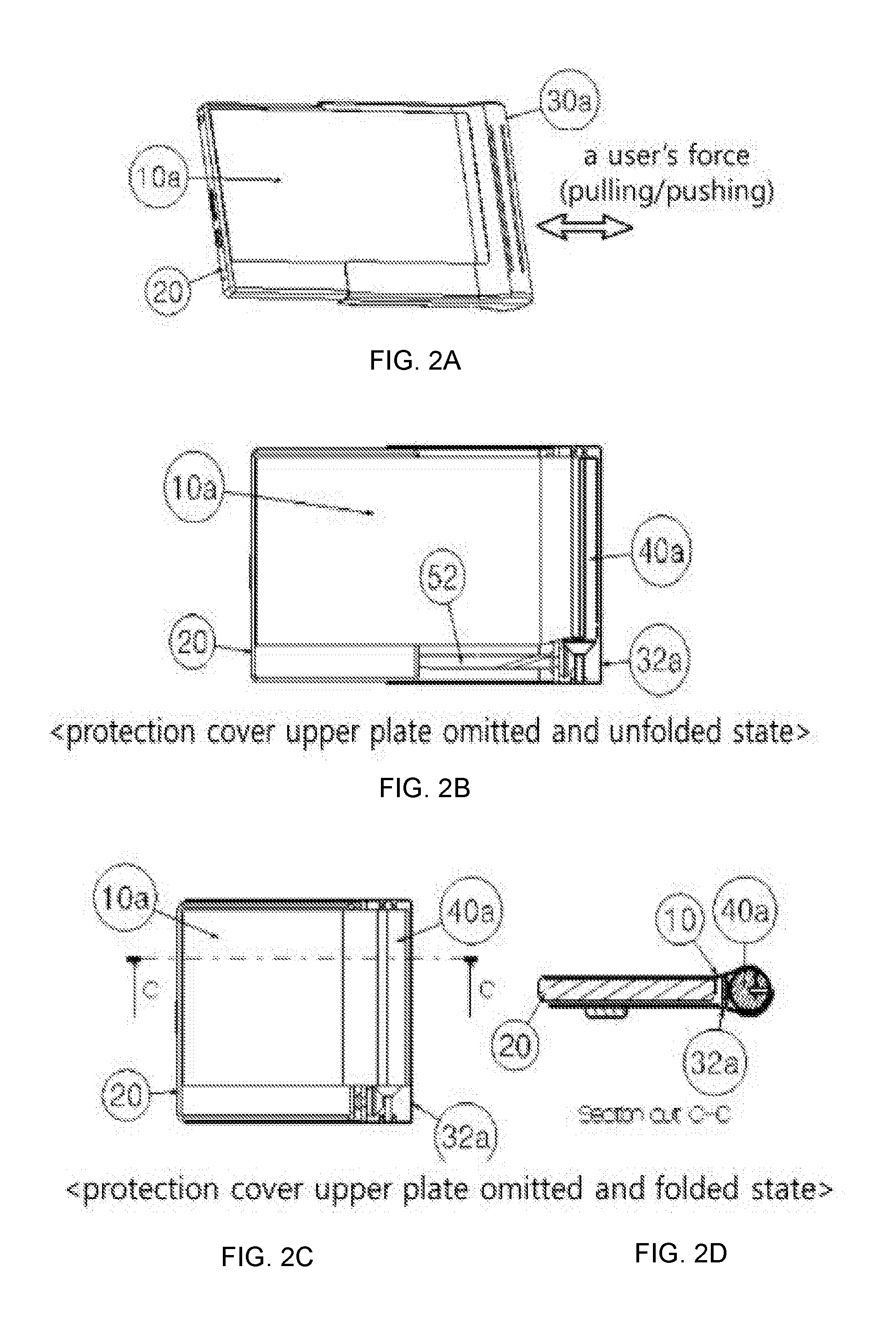
[0032]Referring to FIGS. 2a to 5, a flexible display apparatus 100 according to the present invention includes: a bendable flexible display panel A 10a adapted to have a screen display function; a fixing body 20 adapted to fixedly support a portion of the flexible display panel A 10a thereagainst; a roller A 40a adapted to roll a freely bendable portion of the flexible display panel A 10a and having a gear mounted on one side thereof to transmit a rotational force; a protection cover A 30a slidingly supported against the fixing body 20 in such a manner as to allow the roller A 40a to be rotatably assembled in the interior thereof to protect the flexible display panel A 10a at the inside thereof; and an operating force converter 50 adapted to convert a user's unfolding or folding operating force applied to the flexible display apparatus 100 into a mechanical rotational force to transmit the converted rotational force to the roller A 40a.

second embodiment

[0033]Referring to FIGS. 6a to 9, a flexible display apparatus 100 according to the present invention includes: a bendable flexible display panel B 10b adapted to have a screen display function and having a plurality of conveying through holes 11 linearly spaced apart from each other by a given distance to convey the flexible display panel B 10b; a fixing body 20 adapted to fixedly support a portion of the flexible display panel A 10a thereagainst; a roller B 40b having sprocket type conveying protruding parts 41 mounted on the outside of the circumferential surface of one side end thereof in such a manner as to be continuously locked onto the conveying through holes 11 and a gear mounted on an arbitrary center thereof to transmit a rotational force thereof; a protection cover B 30b slidingly supported against the fixing body 20 in such a manner as to allow the roller B 40b to be rotatably assembled in the interior thereof to protect the portion of flexible display panel B 10b conve...


PUM


Abstract

The present invention relates to a rollable flexible display apparatus to which an operation-force conversion apparatus is applied, wherein the operation-force conversion apparatus converts an unfolding or a folding operation-force linearly applied by a user to a housing of the rollable flexible display apparatus without the application of a motor or a spring into a rotation force with which a roller can rotate using the screw thread principle through an internal mechanical component, and conveys the converted rotational force to the roller.

Description

TECHNICAL FIELD[0001]The present invention relates to a rollable flexible display apparatus, and more particularly, to a flexible display apparatus that is provided with an operating force converter that converts an unfolding or a folding operating force linearly applied by a user when the flexible display apparatus is unfolded or folded by the user into a rotational force for a roller through the principle of a screw thread and thus transmits the converted rotational force to the roller.BACKGROUND ART[0002]A display has an important role in an electronic device including imaging equipment and communication equipment, and with the increment of a user′ desire for portability and conveniences and the development of flexible display panel technologies, a curved flexible display, which is bendable to a given degree, has been shipped. Further, a number of prior arts related to a rollable flexible display or foldable flexible display have been recently suggested.[0003]In case of the exist...

Claims


Application Information

Patent Timeline
Patent Type & Authority Applications(United States)
IPC IPC(8): H05K5/00H05K5/02H05K5/03G09F9/30
CPCH05K5/0017H05K5/03H05K5/0217G09F9/30G06F1/1626G06F1/1637G06F1/1652G06F1/1641G09F9/00
Inventor LIM, YOUSEOB
Owner LIM YOUSEOB
Why Eureka
Try Eureka