Parameter independent detection of rotating machinery faults

a technology of rotating machinery and fault detection, applied in the direction of machine part testing, material analysis using acoustic emission techniques, processing detected response signals, etc., can solve the problems of unplanned productivity loss for production facilities or catastrophic consequences for mission-critical equipment, failure of rolling-element bearings, and complete stalling of mechanical systems. , to achieve the effect of efficient implementation

Inactive Publication Date: 2010-06-10
UNIVERSITY OF OTTAWA
View PDF21 Cites 51 Cited by
  • Summary
  • Abstract
  • Description
  • Claims
  • Application Information

AI Technical Summary

Benefits of technology

[0029]In one embodiment of the invention, a mathematical transformation incorporates an arbitrary combination of ADM, PDM and FDM prior to spectral analysis. Under this approach, no prior analysis parameters are needed and no prior knowledge about t...

Problems solved by technology

The intense loading conditions of bearings and gears together with their harsh operating environment makes them failure-prone.
Bearing failure could lead to the complete stall of a mechanical system, unplanned productivity loss for production facilities or catastrophic consequences for mission-critical equipment.
The failures of rolling-element bearings are often caused by surface faults such as cracks or spalls on bearing rollers or bearing races.
The resulting high frequency resonance is typically damped out quickly due to the structural damping characteristics of the whole system.
However, the raw data signals contain not only the fault related vibrations but also the background noise present in any measurement device, also known as intrinsic noise signals, as well as the vibrations generated by other mechanical components such as gear meshing, shaft imbalance or misalignment, also known as interference signals.
In addition, the target fault characteristic signals are typically of small amplitude compared to the interference and noise signals present in typical raw data signals.
In this manner, damaged or faulty machine bearings are identified.
Step 22 is also necessary because amplitude demodulation of raw vibration signal data contaminated by low frequency high amplitude interference is typically ineffective for detecting bearing faults.
One major disadvantage of the HFR approach is the need to pre-select the band-pass filter parameters 21.
Of concern, the pre-specification of optimal band-pass filter parameters can be difficult, expensive, time consuming and sometimes impossible.
As a result, there is often uncertainty in the optimal value of the band-pass filter parameters.
Even in situations when the optimal band-pass filter parameters are known in principle, problems can still be encountered during actual machine operation, since the machine conditions can change over time.
However, re-selection of the band-pass filter parameters is difficult and time consuming, since the machine conditions can change in a rapid and unpredictable manner.
There is also a possibility that the machine conditions change in the process of the analysis and even before the new filter parameters have been re-selected.
Given the above factors, band-pass filters used in HFR approaches are often considered to be non-optimal and sufficiently broad so as to accommodate uncertainty in the value of the parameters or drift in the machine operating conditions....

Method used


Image

  • Parameter independent detection of rotating machinery faults
  • Parameter independent detection of rotating machinery faults
  • Parameter independent detection of rotating machinery faults

Examples


experiment i

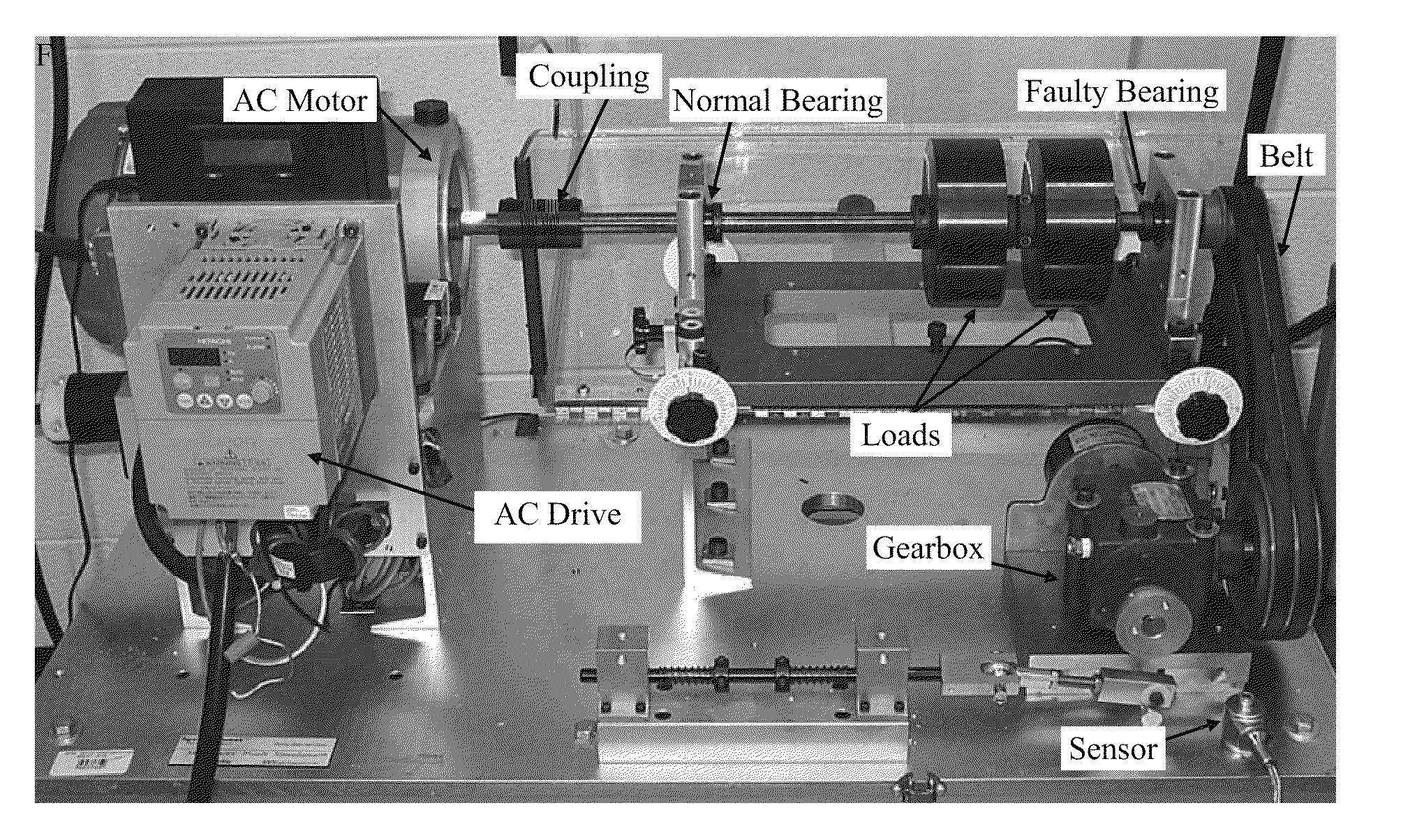
[0068]Referring to FIG. 7, the mechanical system of experiment I, which incorporates a faulty outer-race bearing is illustrated. Experiment I was conducted using a SpectraQuest Machinery Fault Simulator (MFK-PK5M). Attached to the simulator were two well balanced mass rotors (2″ thick, 4″ in diameter and 11.1 lbs each) installed on a ⅝″ steel shaft and supported by two type ER10K bearings (inside, outside, pitch and ball diameters are respectively 0.6250″, 1.8500″, 1.3190″ and 0.3125″) with eight rolling elements (balls). The simulator was powered by a 3-hp AC motor which was controlled by a Hitachi drive (SJ200-022NFU). The shaft speed was set at 1422 RPM (23.7 Hz). The right bearing had a pre-seeded fault created by the manufacturer on the outer race with a characteristic frequency of 72 Hz, as specified in the simulator user's manual. To create additional vibration interference, a gearbox was also connected to the driving shaft using a belt.

[0069]In experiment I, an accelerometer...

experiment ii

[0073]Referring to FIG. 10, the mechanical system of experiment II, driven by an AC motor incorporating a faulty inner-race bearing is illustrated. An AC motor bearing of type NSK-6203 (inside, outside, pitch and ball diameters are respectively 0.6693″, 1.5748″, 1.142″ and 0.266″) with eight rolling elements (balls) was used. A single balanced load rotor (2″ thick, 4″ in diameter and 11.1 lbs) was mounted on the same ⅝″ steel shaft which was used in experiment I. Both bearings that supported the shaft were normal. To introduce additional vibration interferences, two unbalanced rotors were also installed on the ⅝″ steel shaft, as well as a gearbox via a belt connection. The shaft speed was set at 1428 RPM (23.8 Hz). The AC motor bearing had a pre-seeded fault, which was created by the manufacturer on the inner race with a characteristic frequency of 117 Hz.

[0074]In experiment II, the raw vibration sensor data was acquired from the vibration sensor in the same fashion as in experiment...

experiment iii

[0077]The mechanical system of experiment III is illustrated in FIG. 13. This experiment was for a two stage parallel gearbox incorporating a faulty output gear. The faults of the output gear include dented and chipped teeth. Referring to the same figure, the input gear has 24 teeth. This gear engages with a 40 teeth intermediate gear, labeled as “Intermediate 1” in FIG. 13(b), leading to a speed reduction of 0.6. The second intermediate gear, labeled as “Intermediate 2” in FIG. 13(b), has 32 teeth and was engaged to a 96 teeth output gear. Hence, the total speed reduction was 0.2. The output shaft was connected to a Precision Tork™-Model MC6 magnetic break providing 4.7 N.m load. The same accelerometer (Montronix VS100-100) as that used in experiments I and II was placed on the casing of the gearbox, as illustrated in FIG. 13(a).

[0078]In this experiment, the shaft rotational speed was 3.54 Hz, which lead to fundamental harmonics of 3.54 Hz, 2.12 Hz, and 0.71 Hz for the input, inter...


PUM


Abstract

A parameter-free method to analyze sensor signals incorporates two or more of frequency demodulation, amplitude demodulation and phase demodulation of the raw signal data. The resulting signal is transformed to a frequency domain, and target fault characteristics from the demodulated signal are identified. The method is used to detect faults in bearings, gears and other mechanical components.

Description

CROSS REFERENCE TO RELATED APPLICATIONS[0001]This application claims the benefit of U.S. Provisional Patent Application 61 / 119,954 filed on Dec. 4, 2008 which is hereby incorporated by reference in its entirety.FIELD OF THE INVENTION[0002]The present invention pertains to the detection of the faults of rotational machinery components including bearings, gears, shafts, cams, crankshafts and pistons via the analysis of vibration type signals acquired from machinery while in operation. The faults may have impulsive or non-impulsive characteristics.BACKGROUND[0003]The operation of many mechanical systems is based on the transformation of angular motions to other kinds of movement. Rotating machinery components play a crucial role in this process and are frequently used in mechanical systems. As such, effectively detecting the conditions of these components can help to reduce repair costs and maintain reliable and productive operations.[0004]The intense loading conditions of bearings and...

Claims


Application Information

Patent Timeline
IPC IPC(8): G01N29/14
CPCG01N29/14G01N2291/2696G01N29/46G01N29/4454
Inventor LIANG, MINGBOZCHALOOI, IMAN SOLTANI
Owner UNIVERSITY OF OTTAWA
Why Eureka
Try Eureka