Electrical connector providing a better coplanarity for terminal solders

a terminal solder and connector technology, applied in the direction of securing/insulating coupling contact members, fixed connections, coupling device connections, etc., can solve the problem of not saving the space of the pcb, and achieve the effect of better coplanarity of terminal solders

Active Publication Date: 2008-11-04
HON HAI PRECISION IND CO LTD
View PDF6 Cites 20 Cited by
  • Summary
  • Abstract
  • Description
  • Claims
  • Application Information

AI Technical Summary

Benefits of technology

[0006]Accordingly, an object of the present invention is to provide an electrical connector providing a better coplanarity for terminal solders.

Problems solved by technology

More, as the terminal solder portions of the connector are under the bottom of the insulating housing, the whole connector will be disposed on one side of the PCG, which is not benefit for saving the space of the PCB.

Method used


Image

  • Electrical connector providing a better coplanarity for terminal solders
  • Electrical connector providing a better coplanarity for terminal solders
  • Electrical connector providing a better coplanarity for terminal solders

Examples


Embodiment Construction

[0015]Reference will now be made to the drawing figures to describe a preferred embodiment of the present invention in detail.

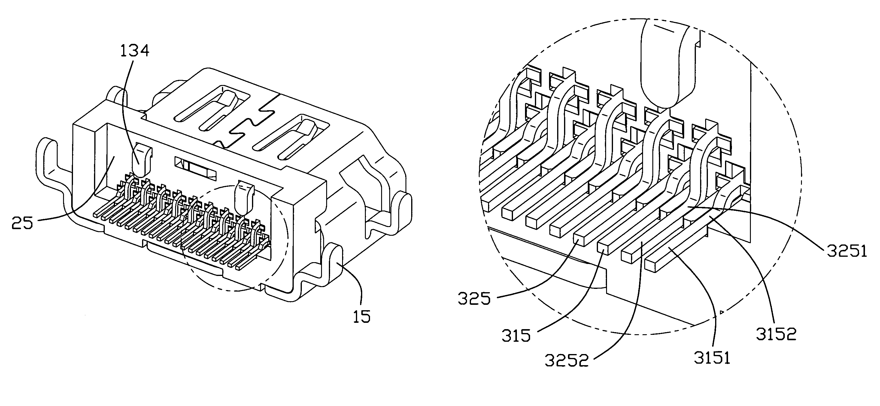
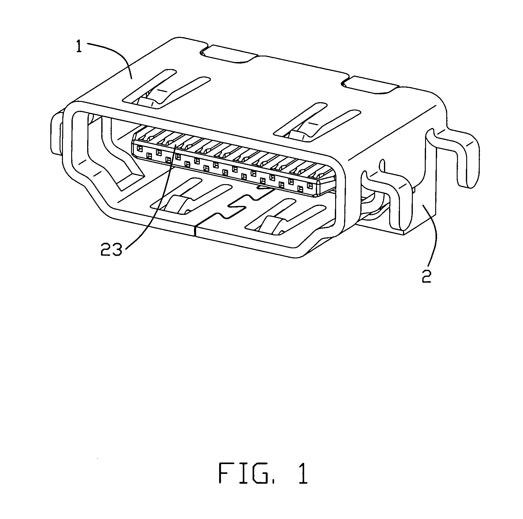
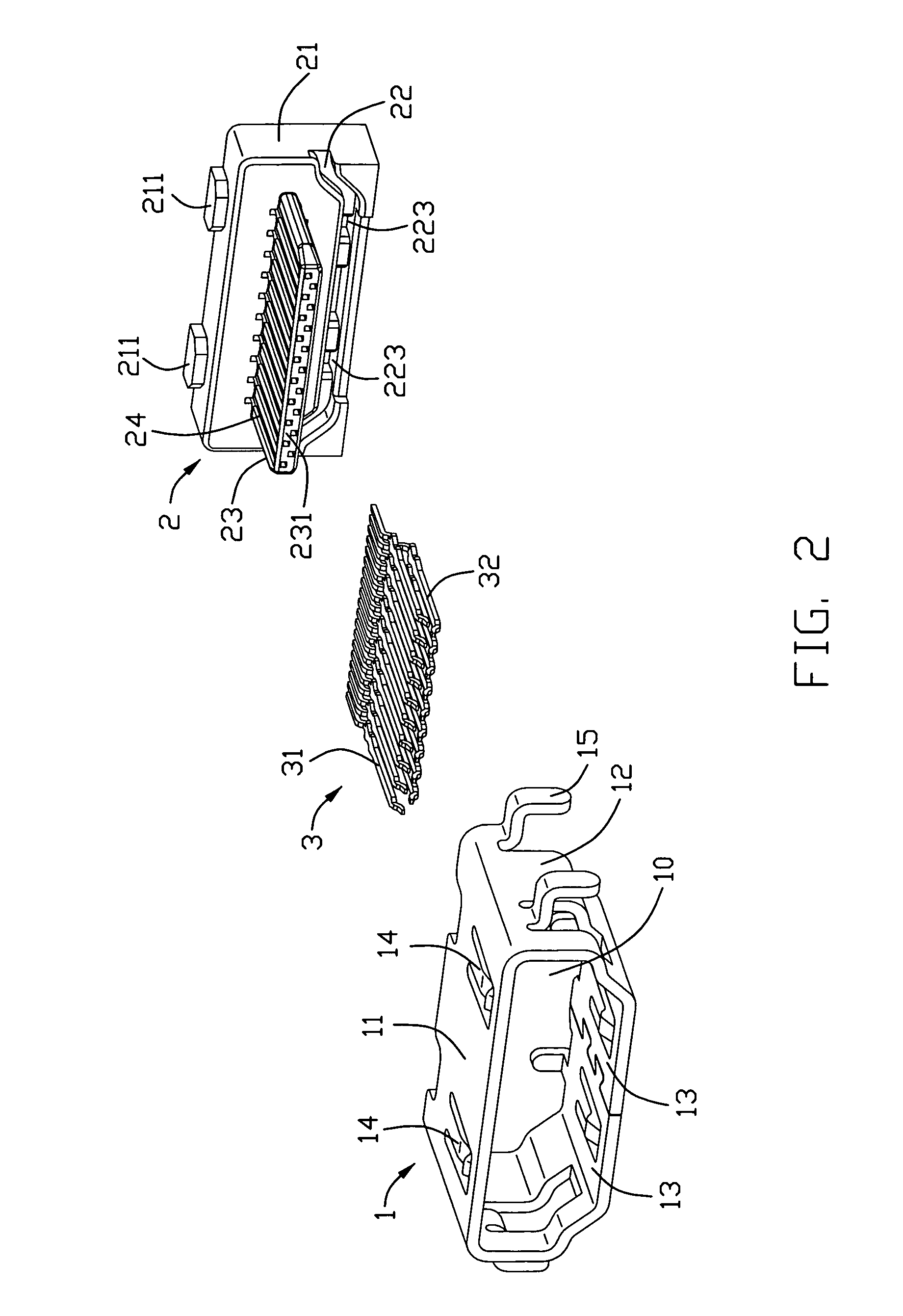
[0016]Referring to FIGS. 1 and 2, an electrical connector in accordance with the present invention comprises a metallic shell 1, an insulating housing 2 and a plurality of terminals 3.

[0017]Referring to FIG. 2, the metallic shell 1 is made by bending a rectangular metal plate and forms a folded structure, defining a receiving space 10 therein. The shell 1 comprises an upper wall 11, a lower wall 13 parallel to and shorter than the upper wall 11 in a transverse direction, and two side walls 12 extending downward from the upper wall and bending inwardly at a lower portion thereof to connect with the lower wall 13. Two resilient sheets 14 are symmetrical formed at opposite ends of the upper wall 11 and lower wall 13 respectively and projecting to the receiving space 10 at each distal end. See FIG. 3, on a back end of the upper wall 11, a pair of slot 111 is open...


PUM


Abstract

An electrical connector of the present invention includes an insulating housing (2) mounting a plurality of terminals (3) and a metallic shell (1) surrounding the insulating housing (2). The insulating housing (2) defines a plurality of terminal grooves (24) therein. A plurality of terminals (3) mounted on the insulating housing (2), each comprises a mating portion (312,322) received in the terminal groove (24) and a solder portion (315,325) extending out of the terminal groove. A terminal solder coplanarity means is provided at a rear portion of the housing.

Description

BACKGROUND OF THE INVENTION[0001]1. Field of the Invention[0002]The present invention relates to an electrical connector, and more particularly to a high definition multimedia interface (HDMI) connector providing a better coplanarity for terminal solders.[0003]2. Description of the Prior Art[0004]Nowadays, Liquid Crystal Displays (LCDs) have become the main choice as the output device for use in Audio / Video (AV) products. The increasing role of LCDs in AV products has created a need for connectors capable of transmitting digital signals between the LCDs and AV products. Therefore, a HDMI connector is provided as a transmission interface utilized for transmitting high definition multimedia digital signals, including high fidelity images and multi-channel audio signals.[0005]U.S. Pat. No. 6,986,681 issued to Tsai on Jan. 17, 2006 discloses a HDMI connector comprising an insulating housing, a metallic shell and a plurality of terminals set in an upper row and a lower row. Each terminal...

Claims


Application Information

Patent Timeline
Patent Type & Authority Patents(United States)
IPC IPC(8): H01R12/00H01R12/55
CPCH01R13/41H01R23/6873H01R12/57H01R13/504H01R13/658
Inventor WU, ZHE-FENG
Owner HON HAI PRECISION IND CO LTD
Why Eureka
Try Eureka