Electrostatic suspension furnace and method for fusing samples using this

a technology of electrostatic suspension and levitation furnace, which is applied in the direction of furnaces, relays, lighting and heating apparatus, etc., can solve the problems of extremely difficult to fuse nonconductors, and each of the temperatures of two samples is not adjusted independently

Inactive Publication Date: 2008-11-04
IHI AEROSPACE CO LTD
View PDF4 Cites 4 Cited by
  • Summary
  • Abstract
  • Description
  • Claims
  • Application Information

AI Technical Summary

Benefits of technology

[0008]The present invention has been made in view of the problems in such a conventional art and an object of the invention is to provide a electrostatic levitation furnace which, for example, when fusing two species of samples together, irrespective of whether or not the samples are conductors, makes the samples melt while levitating them individually and fuses the samples together while maintaining temperatures of the samples respectively, and consequently actualize a fusion in a state excluded external interference, and a method for fusing plural species of samples all together using the same.

Problems solved by technology

The conventional electrostatic levitation furnace mentioned above has the function of melting a sample maintained in a levitation state, but does not have the one of melting two or more species of samples while levitating because of incapable of putting a plurality of samples in a levitation state using one electrostatic field.
On the grounds of above, there is a problem that such fusion does not regard as a fusion in a state excluded from external interference (i.e. in a state avoided the use of a container), and there is also a further problem that each of temperatures of two species of samples is not adjusted independently.
It comes near to stating the obvious that even if using an electromagnetic levitation furnace, it is extremely difficult to make nonconductors fuse due to nonconductor is levitated only in being melted.

Method used


Image

  • Electrostatic suspension furnace and method for fusing samples using this
  • Electrostatic suspension furnace and method for fusing samples using this
  • Electrostatic suspension furnace and method for fusing samples using this

Examples


Embodiment Construction

[0021]The present invention will be explained below with referring to the accompanying drawings. It is to be understood that a detailed constitution of an electrostatic levitation furnace of the invention is not limited to the only following embodiments.

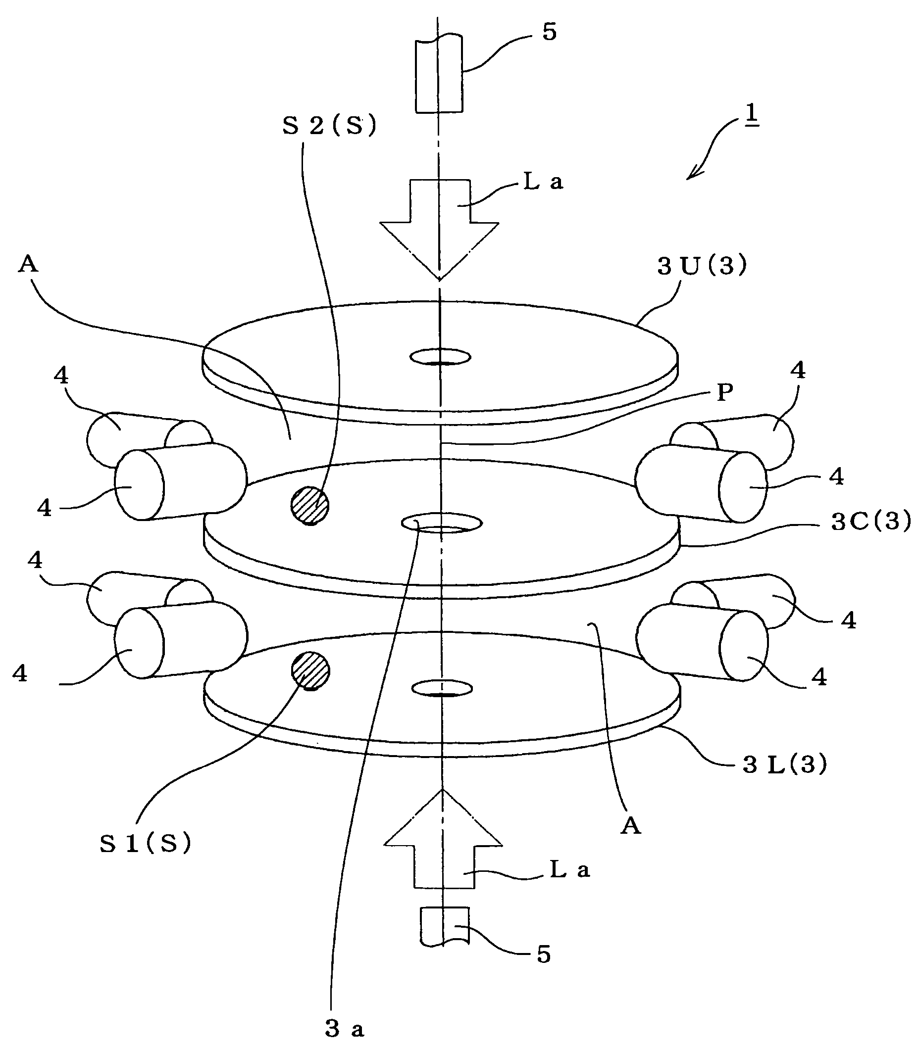
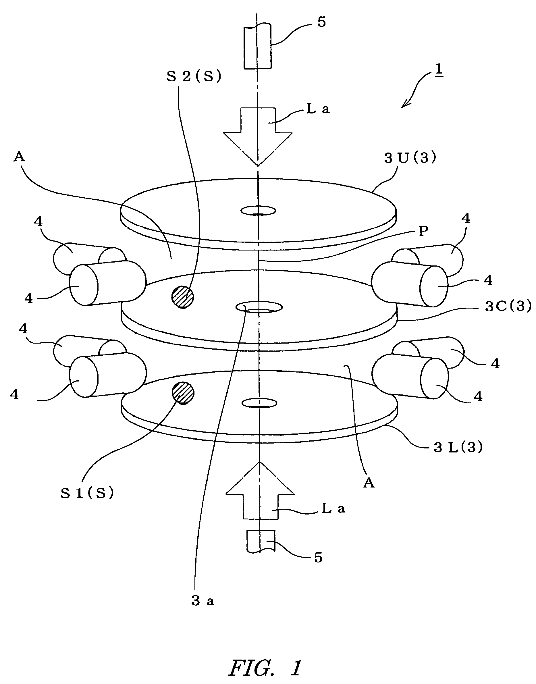
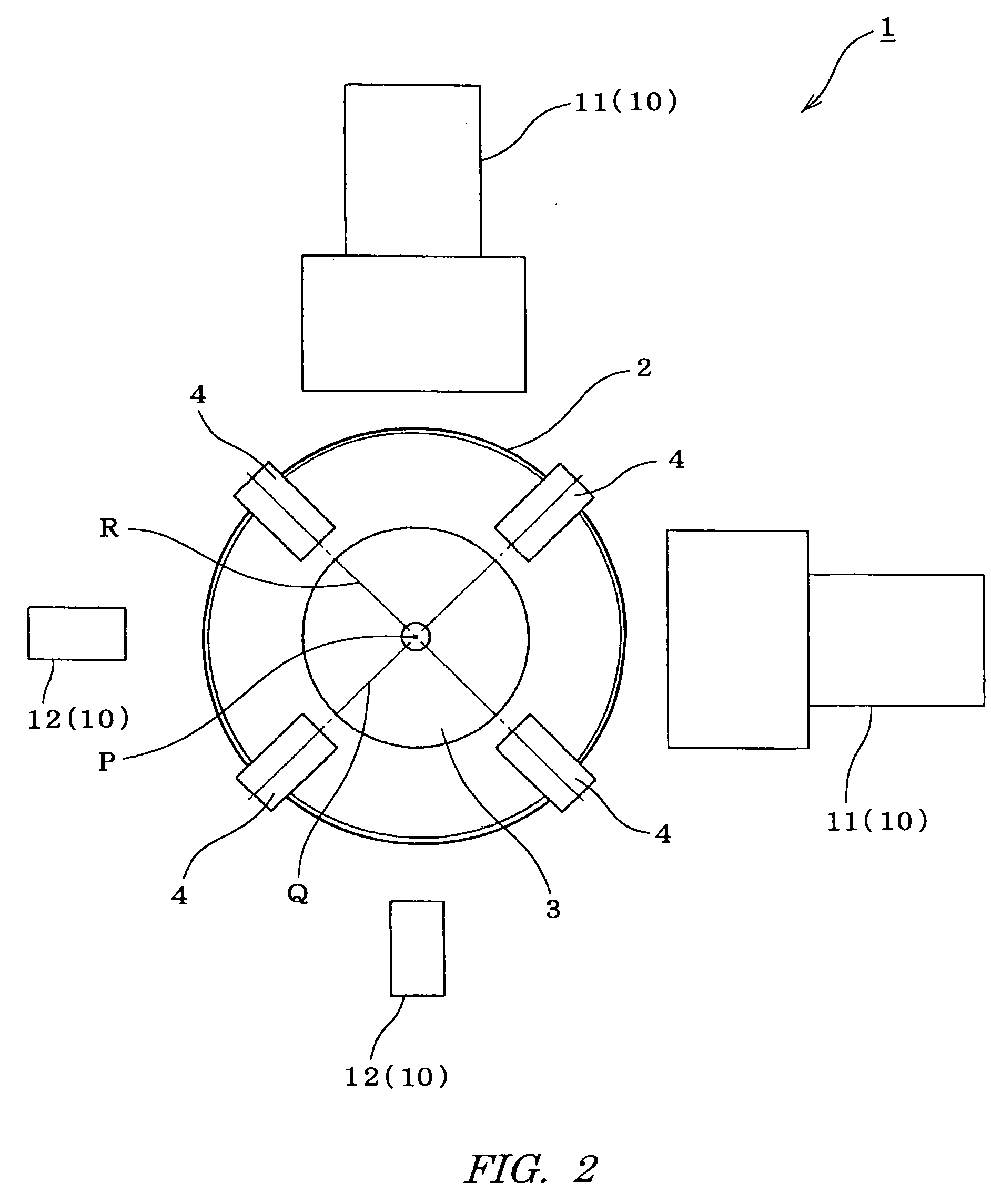
[0022]FIGS. 1 to 4 show one embodiment of an electrostatic levitation furnace of the present invention. As shown FIGS. 1 to 3, the electrostatic levitation furnace 1 is provided with a vacuum chamber 2 (shown in FIG. 2 only), plural (three, in this embodiment) sheets of disc-form main electrodes 3 provided at intervals of 5 to 10 mm in a vertical direction within the vacuum camber 2, where an interspace between the adjacent main electrodes 3 and 3 is defined as an electrostatic filed generating interspace A.

[0023]The electrostatic levitation furnace 1 is provided with an auxiliary electrode 4 displacing a levitated sample S to a predetermined position (on P axis passing through the centers of main electrode 3) by electrostatic field ...


PUM


Abstract

An electrostatic levitation furnace wherein main electrodes opposed to each other within a vacuum chamber are arranged at intervals to form interspaces between them. Auxiliary electrodes are arranged to correspond to each of the electrostatic field generating interspaces, and laser irradiators are arranged above the uppermost main electrode and under the lowermost main electrode, and the main electrode positioned midway between the uppermost and lowest one has a through-hole on an optical path of laser beam which a sample can be passed through. When two species of samples are fused together, regardless of whether or not the samples are conductors, the furnace has the function of melting the levitated samples and fusing them together while maintaining each of the temperatures of the samples, and consequently this permits realization of fusion in a state free of external interference.

Description

[0001]This is a National Stage entry of International Application PCT / JP2004 / 002190, with an international filing date of Feb. 25, 2004, which was published as WO 2004 / 083757 A1, and the complete disclosure of which is incorporated into this application by reference.TECHNICAL FIELD[0002]The present invention relates to an electrostatic levitation furnace for putting a charged sample in a levitation state by electrostatic field generated between electrodes and performing heating process on the sample.BACKGROUND ART[0003]In a conventional art, an electrostatic levitation furnace where a pair of main electrodes is allocated in a flat and approximately cylindrical vacuum chamber on Z axis corresponding to an axis of the chamber, and also a pair of auxiliary electrodes is allocated on each of X axis and Y axis orthogonal to Z axis is well known.[0004]The electrostatic levitation furnace charges a sample which is inputted between main electrodes by electrode contact, ultraviolet irradiati...

Claims


Application Information

Patent Timeline
Patent Type & Authority Patents(United States)
IPC IPC(8): H05B11/00F27B14/04F27B17/00F27D7/06F27D21/02
CPCF27B14/04F27B17/0016
Inventor KAWASAKI, KAZUNORIASAHI, HIROAKI
Owner IHI AEROSPACE CO LTD
Why Eureka
Try Eureka