Mountable bicycle structure

a bicycle and frame technology, applied in the direction of washstands, steering devices, rod connections, etc., can solve the problems of difficult and/or complicated installation of accessories and/or components on the bicycle, inconvenient arrangement for the rider, and difficulty in determining the current gear position of the rider, so as to achieve convenient and reliable mounting

Inactive Publication Date: 2008-11-11
SHIMANO SINGAPORE PRIVATE LTD
View PDF39 Cites 21 Cited by
  • Summary
  • Abstract
  • Description
  • Claims
  • Application Information

AI Technical Summary

Benefits of technology

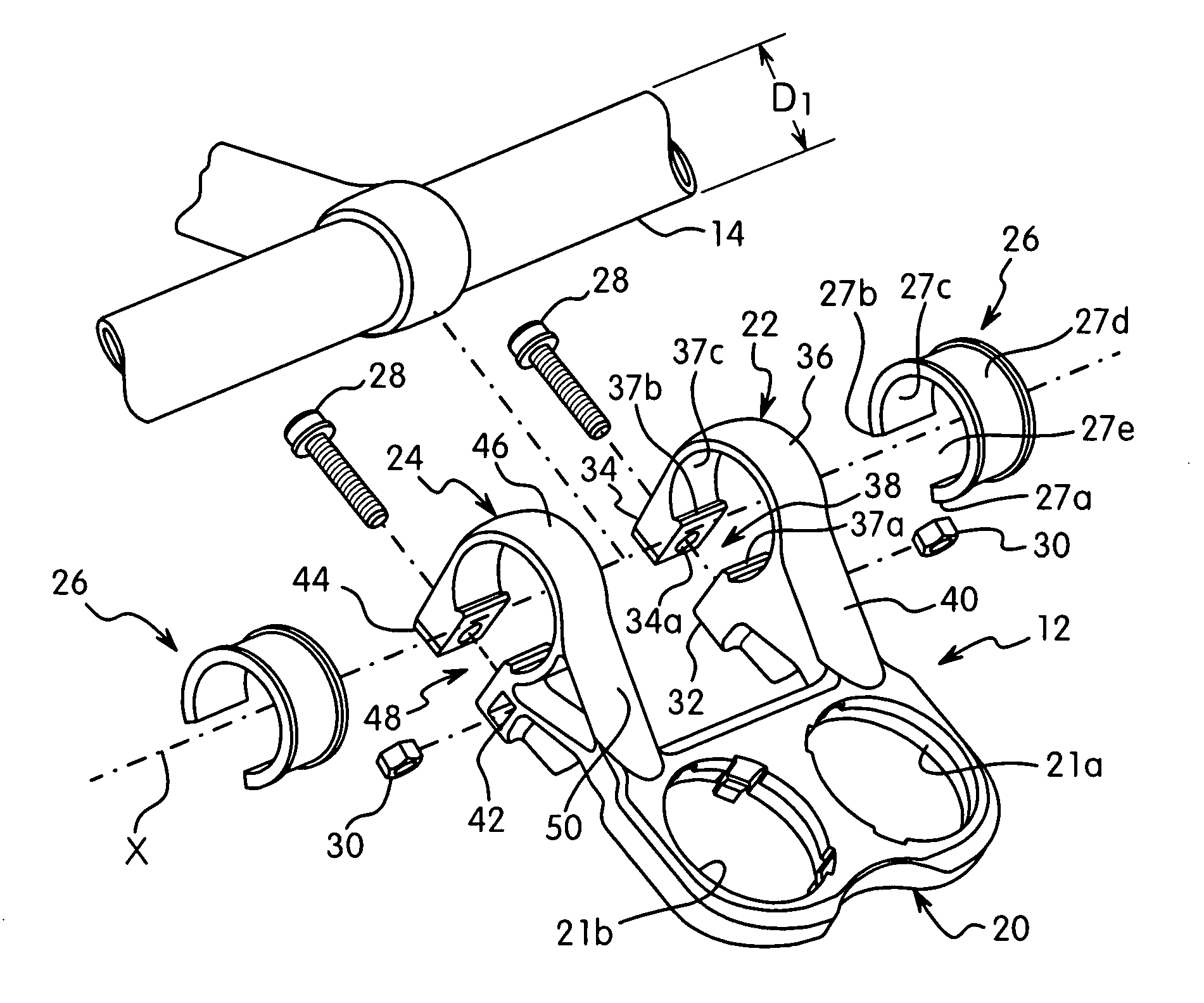
[0008]One object of the present invention is to provide a mountable bicycle structure that can be easily and reliably mounted on a tubular member.
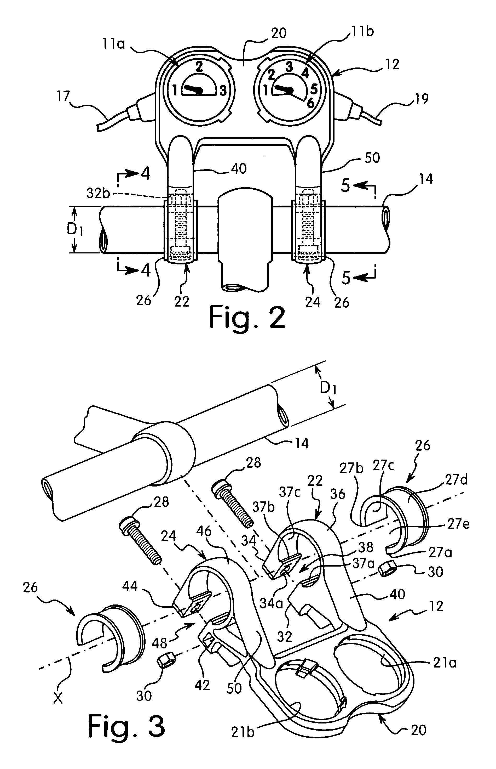
[0009]Another object of the present invention is to provide a mountable bicycle structure that can be easily and reliably mounted on different sized tubular members such as different sized handlebars, and which can be used to support several different components on the different sized handlebars.
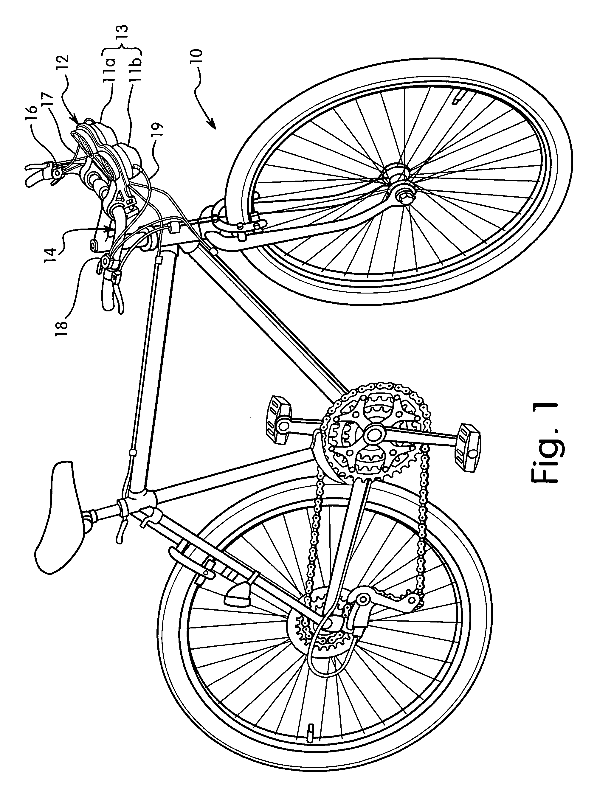
[0010]Another object of the present invention is to provide a mountable bicycle structure that can be easily and rigidly secured on a center portion of the handlebar for easy viewing of a component that is coupled thereto.
[0011]Another object of the present invention is to provide a mountable bicycle structure that is strong, yet relatively lightweight.
[0012]Yet another object of the present invention is to provide a mountable bicycle structure that has a simple structure with relatively few separate parts.
[0013]Still another object of the present invention is to provide a mountable bicycle structure that that is relatively simple and inexpensive to manufacture using conventional manufacturing techniques.

Problems solved by technology

However, this positioning of the shifting units makes it difficult to determine the current gear position for the rider.
This arrangement is inconvenient for the rider.
While all of these devices work relatively well, it can be difficult and / or complicated to install such accessories and / or components on the bicycle, especially on different sized handlebars.
Moreover, these typical accessories and / or components can be relatively complicated and expensive to manufacture and assemble, especially when it is desirable to make these devices compatible with different sized handlebars.

Method used


Image

  • Mountable bicycle structure
  • Mountable bicycle structure
  • Mountable bicycle structure

Examples


second embodiment

[0068]Referring now to FIGS. 17-20, a modified mounting member 212 in accordance with a second embodiment of the present invention will now be explained. This second embodiment is identical to the first embodiment, except that the mounting member 212 is provided with a modified component support portion 220 that supports a bicycle computer 215 in addition to the gear indicator displays 11a and 11b of the first embodiment. In view of the similarity between the first and second embodiments, the parts of the second embodiment that are identical to the parts of the first embodiment will be given the same reference numerals as the parts of the first embodiment. Moreover, the descriptions of the parts of the second embodiment that are identical to the parts of the first embodiment may be omitted for the sake of brevity. Furthermore, it will be apparent to those skilled in the art from this disclosure that the descriptions and illustrations of the first embodiment also apply to this second...

third embodiment

[0070]Referring now to FIGS. 21-23, a modified mounting member 312 in accordance with a third embodiment of the present invention will now be explained. This third embodiment is identical to the first embodiment, except that the mounting member 312 is provided with a modified component support portion 320 that supports a bicycle lamp / light 315 instead of the gear indicator displays 11a and 11b of the first embodiment. In view of the similarity between the first and third embodiments, the parts of the third embodiment that are identical to the parts of the first embodiment will be given the same reference numerals as the parts of the first embodiment. Moreover, the descriptions of the parts of the third embodiment that are identical to the parts of the first embodiment may be omitted for the sake of brevity. Furthermore, it will be apparent to those skilled in the art from this disclosure that the descriptions and illustrations of the first embodiment also apply to this third embodim...


PUM


Abstract

A mountable bicycle structure is provided that can be clamped onto different sized tubular members such as handlebars by using different adapter members. The mountable bicycle structure basically includes a component support portion, a tubular clamping portion, a tightening structure and an adapter member. The tubular clamping portion has a split ring configuration to define an adjustable inner diameter that extends around a center axis. The tightening structure is coupled to first and second ends of the tubular clamping portion to selectively reduce the adjustable inner diameter. The adapter member has a split ring configuration with an outer surface removably arranged on the inner surface of the tubular clamping portion. The tubular clamping portion and the adapter member are arranged and configured to align the split of the adapter member with the attachment slot of the tubular clamping portion.

Description

BACKGROUND OF THE INVENTION[0001]1. Field of the Invention[0002]This invention generally relates to a mountable bicycle structure. More specifically, the present invention relates to a tubular clamping portion of the mountable bicycle structure, which utilizes an adapter in order to easily and reliably secure the mountable bicycle structure onto a bicycle element such as a handlebar.[0003]2. Background Information[0004]Bicycling is becoming an increasingly more popular form of recreation as well as a means of transportation. Moreover, bicycling has become a very popular competitive sport for both amateurs and professionals. Whether the bicycle is used for recreation, transportation or competition, the bicycle industry is constantly improving the various components of the bicycle. Additionally, bicycles are constantly being designed so as to be more ergonomic and user friendly. In particular, various additional accessories and / or improved components have been developed in recent year...

Claims


Application Information

Patent Timeline
Patent Type & Authority Patents(United States)
IPC IPC(8): B62K21/12F16B2/10F16D1/10B62J99/00
CPCB62J11/00B62J99/00B62J2099/0026B62J2099/0033Y10T403/7062Y10T74/20822Y10T403/535Y10T403/7098Y10T24/1453Y10T403/53B62J50/22B62J50/225
Inventor TIONG, KHOO KEAN
Owner SHIMANO SINGAPORE PRIVATE LTD
Why Eureka
Try Eureka