Powered personnel ascender

a technology of power ascender and power rope, which is applied in the direction of portable lifting, transportation and packaging, hoisting equipment, etc., can solve the problems of injury or death, limit the length and weight of rope that can be used, and limit the operation of climber operated winches, so as to reduce the starting torque of the motor, reduce the rpm of the capstan, and reduce the grip

Inactive Publication Date: 2008-11-11
QUOIN INT
View PDF16 Cites 28 Cited by
  • Summary
  • Abstract
  • Description
  • Claims
  • Application Information

AI Technical Summary

Benefits of technology

[0014]A powered rope ascender capable of supporting an operator has a motor driven capstan drum to engage the rope. A tension roller forces a pinch roller to grip the rope on the capstan. A centrifugal clutch reduces the starting torque of the motor and services as a brake drum for an integrated brake. A harmonic drive is used to reduce the rpm's of the capstan relative to the motor. A spring loaded load limiting assembly reduces the grip force by the pinch roller when the load supported by the ascender exceeds a predetermined amount and provides for rope slippage during dynamic loading from starting and stopping ascent and descent. The powered rope ascender can be threaded on a rope without access to a rope end.
[0024]Another aspect of the invention is a centrifugal clutch mounted in the brake drum, where the centrifugal clutch is coupled to the motor, where the centrifugal clutch is adapted to engage the inner drum surface, and where the centrifugal clutch is adapted to reduce the starting torque required by the motor.
[0033]A still further aspect of the invention is where the means for limiting load comprises a tension arm having distal and proximal ends, the proximal end coupled to the means for engaging a rope, where the distal end of the tension arm is adapted to move in a first direction, where the means for engaging a rope is adapted to reduce the grip on the rope when the distal end of the tension arm is moved in the first direction, a load bracket having a pivot dowel, a support dowel and a load aperture, the load bracket coupled to the base plate at the pivot dowel, a spring loaded support assembly coupled to the base plate, the spring loaded support assembly adapted to support the load bracket at the support dowel, where the spring loaded support assembly is adapted to react with the distal end of the tension arm, and where the spring loaded support assembly is adapted to move the distal end of the tension arm in the first direction thereby causing the means for engaging a rope to reduce the grip on the rope when the load supported in the load aperture exceeds a predetermined amount.
[0039]A further aspect of the invention is a brake coupled to the base plate, a brake drum coupled between the capstan drum and the motor, where the brake drum has an inner and outer drum surface, where the brake is adapted to engage the outer drum surface, a centrifugal clutch mounted in the brake drum, where the centrifugal clutch is coupled to the motor, where the centrifugal clutch is adapted to engage the inner drum surface, and where the centrifugal clutch is adapted to reduce the starting torque required by the motor.

Problems solved by technology

Further, a winch winds the rope or cable on a spool which limits the length and weight of rope that can be used.
Portable, climber operated winches are limited by bulky power delivery systems and associated weight of the spool.
Failure of a component that results in a rapid descent or fall will result in injury or death.
These devices can cause a sudden stop with resulting injury or equipment damage.

Method used


Image

  • Powered personnel ascender
  • Powered personnel ascender
  • Powered personnel ascender

Examples


Embodiment Construction

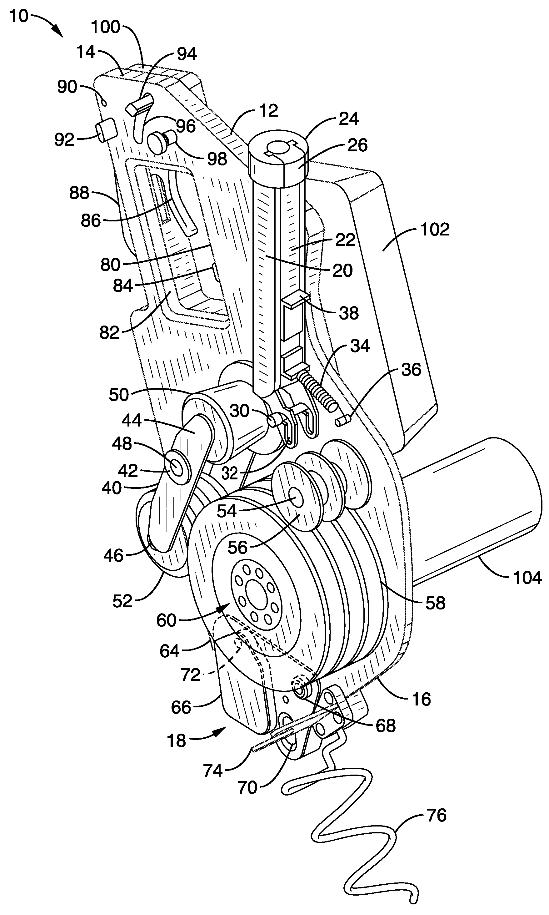
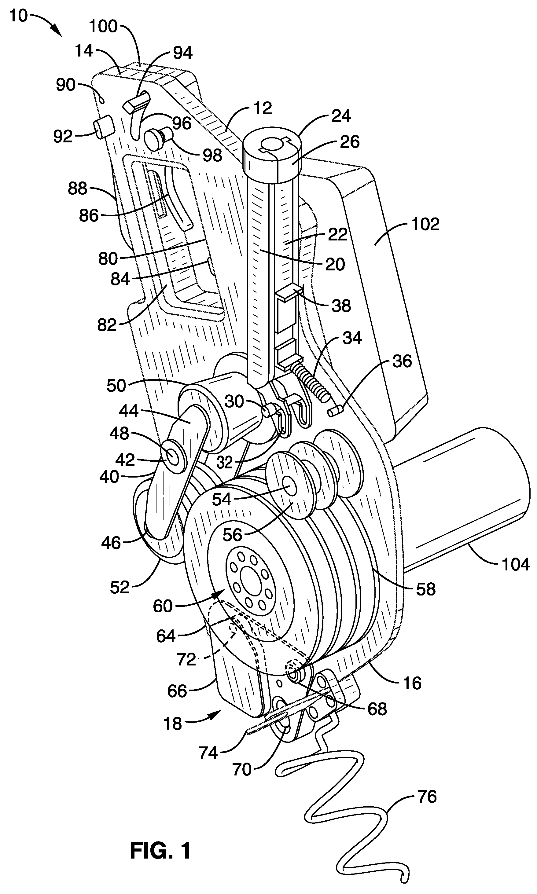
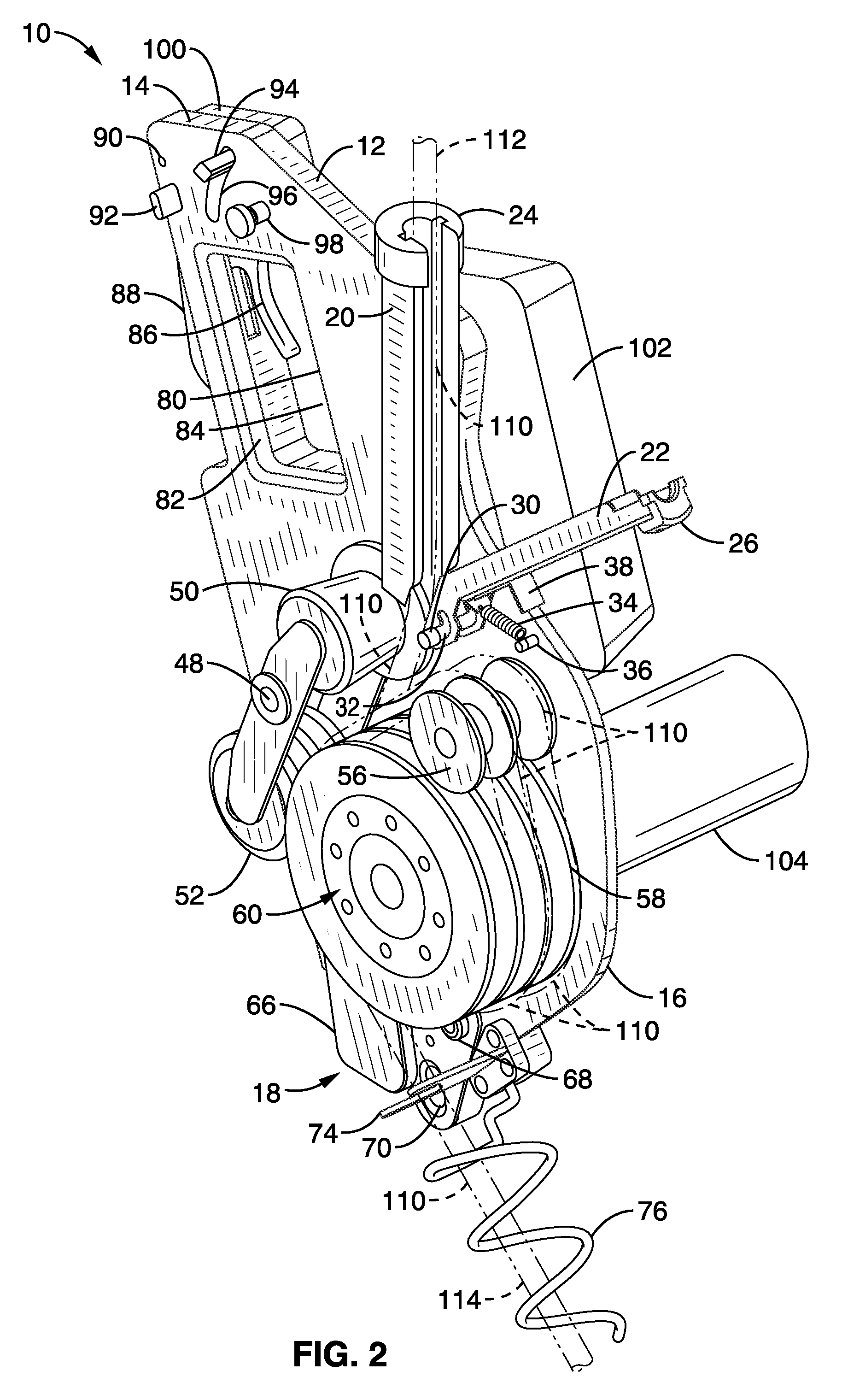
[0067]Referring more specifically to the drawings, for illustrative purposes the present invention is embodied in the apparatus generally shown in FIG. 1 through FIG. 15. It will be appreciated that the apparatus may vary as to configuration and as to details of the parts, and that the method may vary as to the specific steps and sequence, without departing from the basic concepts as disclosed herein.

[0068]FIG. 1 illustrates a schematic capstan side view of a powered rope ascender generally designated as 10. Safety housings are omitted for clarity. Rope ascender 10 has a base plate 12 with a top end 14 and bottom end 16. Although illustrated here as one component, base plate 12 can be assembled from multiple components without departing from the invention. A load limiting assembly 18 is positioned at the bottom end 16 of base plate 12 and will be described in detail in FIG. 7A and FIG. 7B. An up rope fixed channel 20 is attached to base plate 12 with a moveable channel 22 adapted to...


PUM


Abstract

A powered rope ascender that supports a person or a load while ascending a vertical rope. The rope ascender has a motor driven capstan drum that engages the rope. A pinch roller grips the rope against the capstan drum. A load limiting assembly releases the grip by the pinch roller when the load supported by the ascender exceeds a predetermined amount. A centrifugal clutch reduces starting torque required by the motor and the outer drum of the centrifugal clutch interacts with a brake to hold position on the rope. For heavy loads a motion activated brake is used. Hand controls provide a freewheeling, a braking and an ascending mode of operation. A harmonic drive or planetary reduction gears provide speed reduction from the motor to the capstan drum. The powered rope ascender can be threaded on the rope without access to a rope end.

Description

CROSS-REFERENCE TO RELATED APPLICATIONS[0001]This application claims priority from, and is a 35 U.S.C. §111(a) continuation of, co-pending PCT international application Ser. No. PCT / US2006 / 000220, filed on Jan. 4, 2006, incorporated herein by reference in its entirety, which claims priority from U.S. provisional application Ser. No. 60 / 696,382, filed on Jul. 1, 2005, incorporated herein by reference in its entirety, PCT International Application Serial No. PCT / US2005 / 015954, filed on May 6, 2005, incorporated herein by reference in its entirety, U.S. provisional application Ser. No. 60 / 656,605, filed on Feb. 25, 2005, incorporated herein by reference in its entirety, and U.S. provisional application Ser. No. 60 / 642,270 filed on Jan. 6, 2005, incorporated herein by reference in its entirety.[0002]This application is related to PCT International Publication No. WO 2006 / 074250 A2, published on Jul. 13, 2006, incorporated herein by reference in its entirety, and to PCT International Pub...

Claims


Application Information

Patent Timeline
Patent Type & Authority Patents(United States)
IPC IPC(8): B66D1/50
CPCB66B9/00
Inventor JACOBSON, MICHAEL D.WALTER, TIM
Owner QUOIN INT
Why Eureka
Try Eureka