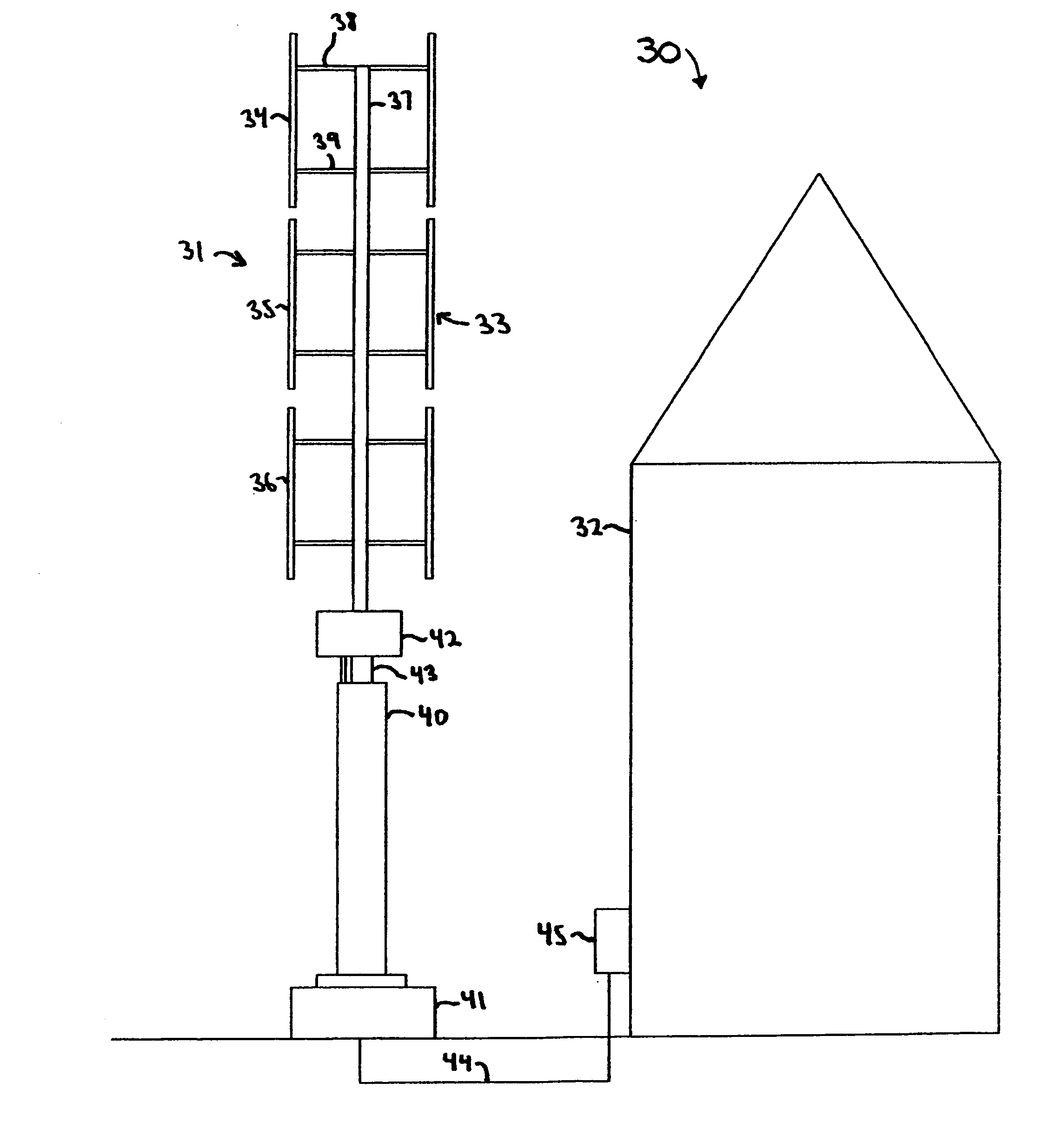
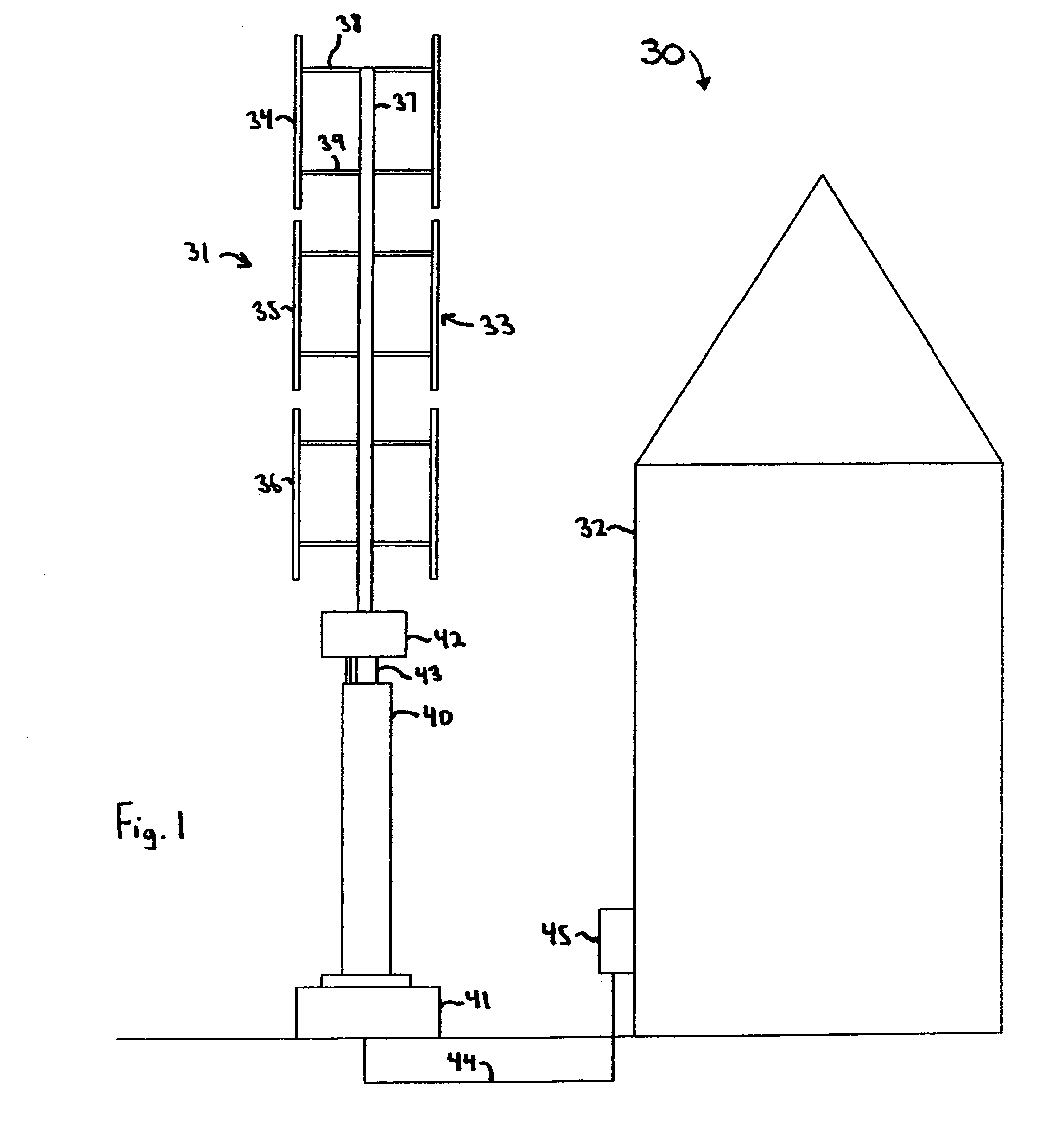
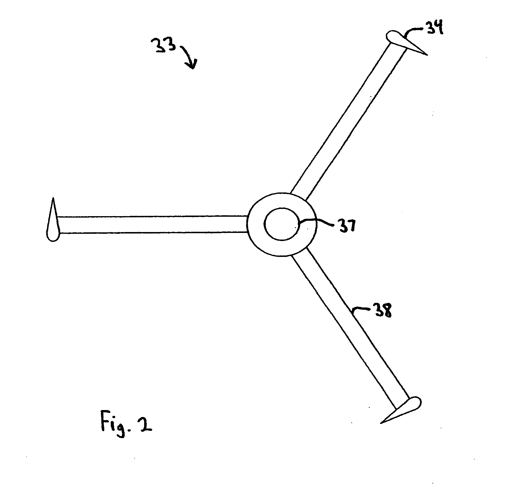
[0010]The self-starting Darrieus wind turbine comprises a Darrieus rotor, and an alternator, electronic controller and a bearing system that cooperate to facilitate passive self-starting. The Darrieus rotor is supported by the bearing system to rotate about a
vertical axis for capturing wind energy. The alternator is directly-driven by the Darrieus rotor and converts rotational power from the Darrieus rotor into electrical power, whereby the electronic controller controls the
electrical load that is applied to the alternator and the power that is delivered to an output. The alternator is constructed of a
permanent magnet rotor and an aircore armature, wherein magnets on the
permanent magnet rotor drive
magnetic flux across an armature airgap, and the aircore armature is constructed of windings in a substantially non-ferromagnetic structure where located inside the armature airgap. The bearing system comprises upper and lower rolling element mechanical bearings and a
magnetic bearing. The mechanical bearings provide radial support of the Darrieus rotor against wind load and axial support of the rotor. The
magnetic bearing provides axial lift that reduces the weight on the mechanical bearings and reduces the starting torque for rotating the Darrieus rotor. The electronic controller further applies substantially no electrical load to the alternator until the Darrieus rotor is at a rotational speed greater than the
deadband for the Darrieus rotor in the instantaneous
wind speed.
[0012]Rolling element mechanical bearings provide support of the Darrieus rotor against the radial wind loads and some axial support of the rotor weight. The axial magnetic bearing removes the majority of the
axial load from the mechanical bearings. A magnetic bearing system alone, without mechanical bearings, would provide the lowest possible friction, however we have found this construction to be impractical to
resist the high wind loading, and would be costly. Starting friction is reduced in the wind turbine in low wind when starting is most difficult, because there are very low radial loads exerted by the light winds that must be carried by the mechanical bearings. At the same time, the magnetic bearing carries the majority of the rotor weight (axial loading) to substantially reduce friction. The mechanical bearings essentially carry almost no radial or axial loads in the conditions of low wind. A small
axial load on the mechanical bearings is used to stabilize the magnetic bearing and preclude the need for complex, costly and less reliable active electronic control systems. The axial load on the mechanical bearings can be reduced by as much as a factor of 20 to assist the self-starting.
[0014]The magnetic bearing that removes the majority of axial load from the mechanical bearings can have several different constructions. It can be constructed from two magnets to form a repulsive lift bearing or can use one or more magnets and a ferromagnetic yoke to create an attractive lift magnetic bearing. We have found that an attractive arrangement magnetic bearing can provide more than twice the lifting force capability per
magnet size compared to a repulsive lift version and has benefits of lower costs and size. An attractive magnetic bearing can be constructed as a permanent magnetic bearing or an electromagnetic bearing. The use of a permanent
magnet for the field flux is preferred because it allows for a larger magnetic airgap and physical clearance. This allows for reduced
machining tolerances and alleviates concerns about mechanical deflections of assemblies during the turbine operation. The use of a permanent
magnet further simplifies operation and does not require power for operation. In one embodiment of the invention, the magnetic bearing provides axial lift through magnetic attraction between a permanent magnet and a ferromagnetic yoke. A completely defined magnetic path has been shown to provide the highest magnetic lift per
assembly cost. Although the magnetic bearing can be constructed and installed by several means, it is would be desirable to preclude any possibility of human injury from magnetic forces. In an additional embodiment, the magnetic bearing is a single unit
assembly prior to installation whereby
axial force against the mechanical bearings from installation causes the magnetic bearing to form a magnetic airgap. In this construction, the magnetic bearing is magnetically shorted prior to installation. When tightened into place, the magnetic bearing is forced open to form its magnetic airgap.
[0015]The load on the mechanical bearings, which are required for handling the high radial wind load forces in storms, directly affects their friction and starting torque. In low wind conditions, the radial loads of the wind on the Darrieus rotor are small. The majority load is resultantly from the weight of the
turbine rotor. The magnetic bearing is used to remove this load. The starting torque of the rotor is directly related to the axial loading on the mechanical bearings. In one embodiment, the magnetic bearing reduces the starting torque of the Darrieus rotor by more than 50%. More preferably, the installation of the magnetic bearing reduces the starting torque by 95%. To accomplish this reduction in starting torque, the magnetic bearing preferably carries a majority of the weight of the rotor, instead of the mechanical bearings. In an additional embodiment, the mechanical bearings carry an axial load that is less than 10% of the weight of the rotating
mass of the Darrieus wind turbine.
[0018]There are many possible configurations for the construction of a Darrieus wind turbine. These configurations include shafts, bearing locations and the generator position. Traditional Darrieus turbines have utilized a bearing at the top of the rotor shaft and guy wires for upper support. The design of a wind turbine can be very detailed with many considerations. Some configurations can provide additional benefits and
cost savings that might not be expected. In an additional embodiment, the alternator is located axially in between the Darrieus rotor and the upper mechanical bearing. With two mechanical bearings below the alternator and the Darrieus rotor, the alternator can easily be constructed as an outside rotor topology. In contract with most electrical machines, the rotor can be made to rotate about a center
stator. The benefits of this construction include a higher magnet speed and lower costs per
power rating.


