Direct-acting swing hydraulic actuator for articulated robot

A hydraulic actuation and robot technology, applied in manipulators, program-controlled manipulators, manufacturing tools, etc., can solve problems such as large starting friction, difficult sealing, large size, etc., to reduce starting friction, reduce friction, improve servo performance effect

Active Publication Date: 2021-11-26
HARBIN INST OF TECH
View PDF9 Cites 0 Cited by
  • Summary
  • Abstract
  • Description
  • Claims
  • Application Information

AI Technical Summary

Problems solved by technology

[0005] In order to overcome the problems of difficult sealing, large starting friction, large weight, and large size of the direct swing hydraulic actuator in the prior art, the present invention further provides a direct swing hydraulic actuator for articulated robots

Method used


Image

  • Direct-acting swing hydraulic actuator for articulated robot
  • Direct-acting swing hydraulic actuator for articulated robot
  • Direct-acting swing hydraulic actuator for articulated robot

Examples


specific Embodiment approach 1

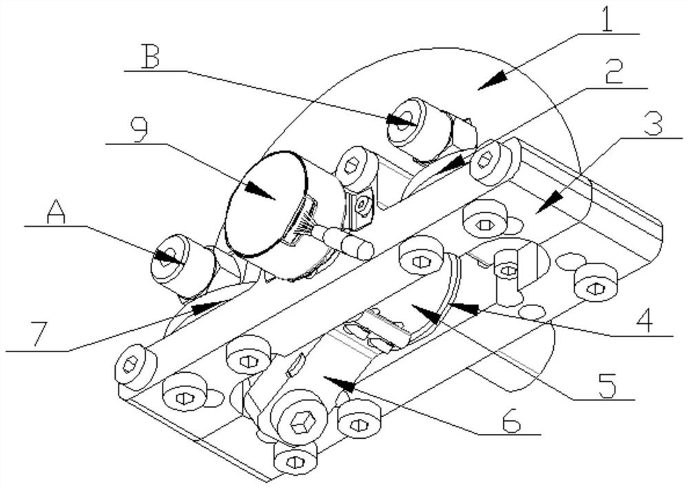
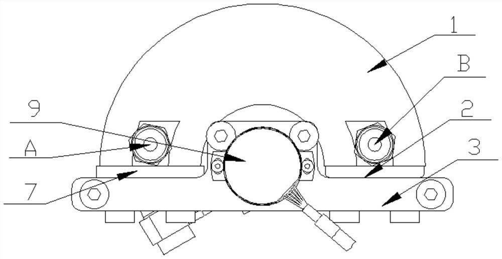
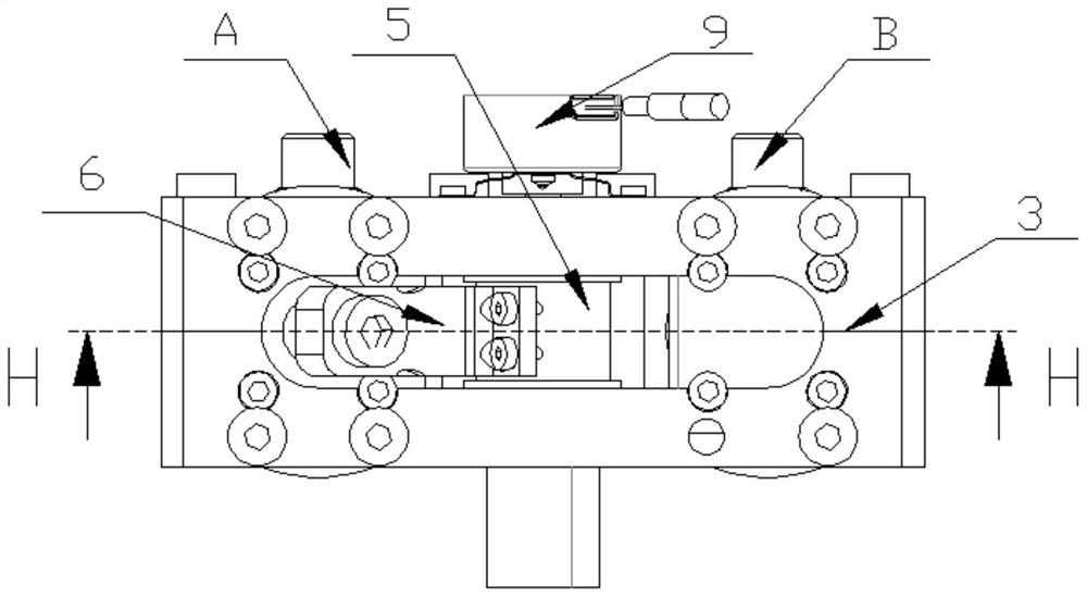
[0022] Specific implementation mode one: combine Figure 1 to Figure 5 Describe this embodiment, a direct-acting swing hydraulic actuator for an articulated robot in this embodiment, which includes an arc-shaped cylinder body 1, a rear end cover 2, a base 3, a flanged bushing 4, a swing shaft 5, Swing connecting rod 6, front end cover 7, encoder 9, arc blade 15 and arc blade connecting rod 16;

[0023] The base 3 is convex and the middle part of the base 3 is provided with a through groove, the inside of the arc-shaped cylinder 1 is an arc-shaped cavity, and the through-groove and the arc-shaped cylinder 1 are arranged corresponding to each other;

[0024] The lower end surface of the front end cover 7 and the lower end surface of the rear end cover 2 are sequentially arranged on the two ends of the same side of the upper end surface of the base 3 along the length direction of the base 3 from left to right, and the arc-shaped cylinder 1 passes through the length direction of t...

specific Embodiment approach 2

[0027] Specific implementation mode two: combination Figure 4 Describe this embodiment, it also includes the first guide ring 12 of the blade and the second guide ring 14 of the blade in this embodiment;

[0028] The both sides of the outer circumferential surface of arc-shaped blade 15 are respectively sleeved with blade first road guide ring 12 and blade second road guide ring 14, and the outer side wall of blade first road guide ring 12 and the blade second road guide ring 14 The outer sidewalls are slidingly arranged relative to the inner sidewall of the arc-shaped cavity, and the first guide ring 12 of the blade is located on one side of the rear end cover 2 .

[0029] The arrangement of the first guide ring 12 and the second guide ring 14 of the vanes can ensure that the arc vanes 15 do not directly contact and rub against the inner wall of the arc cylinder 1, thereby improving their life and reducing friction. Others are the same as the first embodiment.

specific Embodiment approach 3

[0030] Specific implementation mode three: combination Figure 4 To illustrate this embodiment, it also includes a blade sealing ring 13 in this embodiment,

[0031] The outer peripheral surface of the arc-shaped blade 15 is covered with a blade sealing ring 13 , and the blade sealing ring 13 is located between the first blade guide ring 12 and the second blade guide ring 14 .

[0032] Such setting is to reduce frictional force while ensuring sealing.

[0033] Others are the same as those in Embodiment 1 or 2.


PUM


Abstract

The invention discloses a direct-acting swing hydraulic actuator for an articulated robot. In particular to a swing hydraulic actuator which aims at solving the problems that a direct swing hydraulic actuator in the prior art is difficult to seal, large in starting friction force, large in weight and large in size. The outer side wall of an arc-shaped blade is slidably arranged in an arc-shaped cavity, the end of one end of the arc-shaped blade is matched with one side of the upper end of a rear end cover, an arc-shaped blade connecting rod is located in the arc-shaped cavity, and the end of the other end of the arc-shaped blade is in threaded connection with the end of one end of the arc-shaped blade connecting rod. The end of the other end of the arc-shaped blade connecting rod penetrates through an arc-shaped inner hole to be in threaded connection with one end of a swing connecting rod, the other end of the swing connecting rod is fixedly connected with the outer side wall of one side of the middle of a swing shaft in the length direction, and the outer circumferential surface of the middle of the swing shaft is sleeved with a flanging shaft sleeve to achieve circumferential and axial constraint of the swing shaft. The side, away from the encoder, of the flanging shaft sleeve is adjacent to the swing connecting rod. The direct-acting swing hydraulic actuator is used for achieving swing or rotation of the articulated robot.

Description

technical field [0001] The invention relates to the technical field of industrial production, in particular to a direct-acting swing hydraulic actuator for an articulated robot. Background technique [0002] Hydraulic actuators can be divided into two categories according to the output motion form. The first category is hydraulic actuators that output linear motion, such as various linear hydraulic cylinders; the second category is hydraulic actuators that output rotary or swing motions. Devices, such as vane hydraulic motors, gear hydraulic motors, vane swing cylinders, helical swing cylinders, etc. Among them, hydraulic actuators that output rotary or swing motion can be divided into direct swing or rotary hydraulic actuators and indirect swing or rotary hydraulic actuators according to whether there is a transmission mechanism. Indirect oscillating or rotating hydraulic actuators are essentially linear hydraulic actuators that convert the linear motion and force output b...

Claims


Application Information

Patent Timeline
IPC IPC(8): B25J9/14
CPCB25J9/148
Inventor 丛大成李加启杨志东杨宇张燕燕江磊
Owner HARBIN INST OF TECH
Why Eureka
Try Eureka