Working mechanism for construction machine

a technology of working mechanism and construction machine, which is applied in the direction of cranes, lifting devices, constructions, etc., can solve the problems of limited traveling distance (an offset value) and increased size of the entire working mechanism, and achieves the reduction of size and weight of the working mechanism, easy release, and cost reduction

Inactive Publication Date: 2008-11-18
NIHON KENKI CO LTD
View PDF9 Cites 7 Cited by
  • Summary
  • Abstract
  • Description
  • Claims
  • Application Information

AI Technical Summary

Benefits of technology

[0011]In view of the above-discussed problems with the prior art, one object of the present invention is to provide a working mechanism for a construction machine, for which the size and the weight of a link is reduced while a satisfactory strength is obtained for the link, and for which downsizing and weight reduction are promoted, without limiting the left or right distance traveled by a third boom.

Problems solved by technology

Therefore, for example, a large cross-sectional area (the outer diameter) and a large weight for the link are required, and accordingly, there is a problem that the size of the entire working mechanism is increased.
Thus, when the third boom is moved to the left or right side within a range wherein the second boom and the link do not interfere with each other, there is a problem that the traveling distance (an offset value) is limited.

Method used


Image

  • Working mechanism for construction machine
  • Working mechanism for construction machine
  • Working mechanism for construction machine

Examples


first embodiment

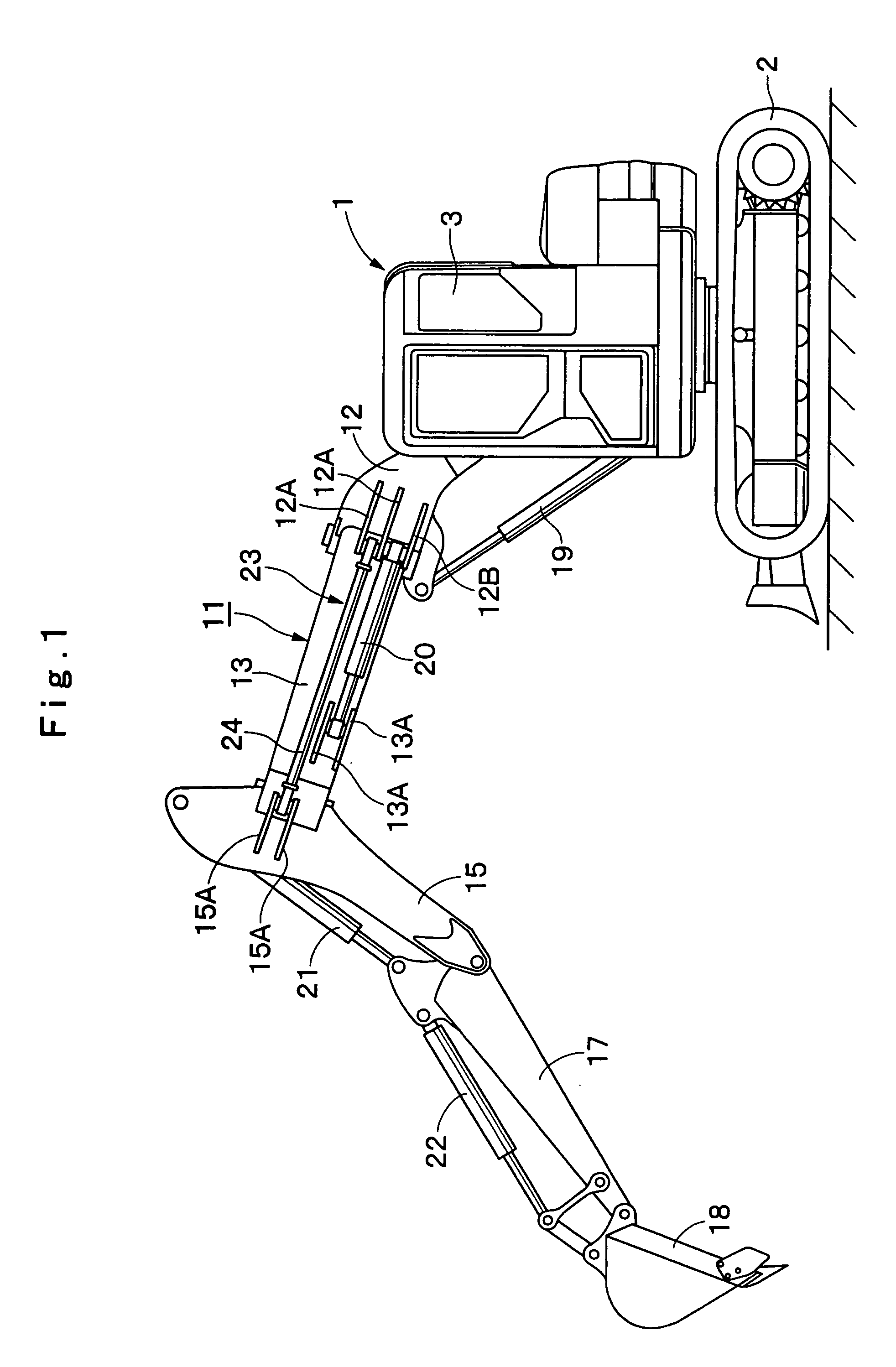
[0051]In the drawings, reference numeral 1 denotes an offset boom type hydraulic excavator as a construction machine applied for the The hydraulic excavator 1 is largely constituted by an automotive vehicular lower structure 2, an upper revolving structure 3 which is rotatably mounted on the vehicular lower structure 2 and constitutes a vehicle body together with the vehicular lower structure 2, and a working mechanism 11 which will be described after.

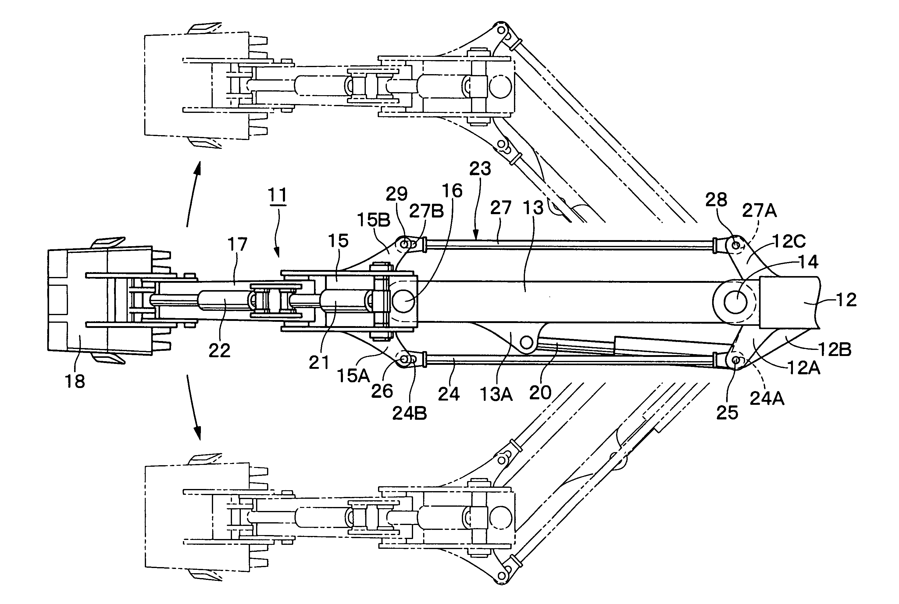
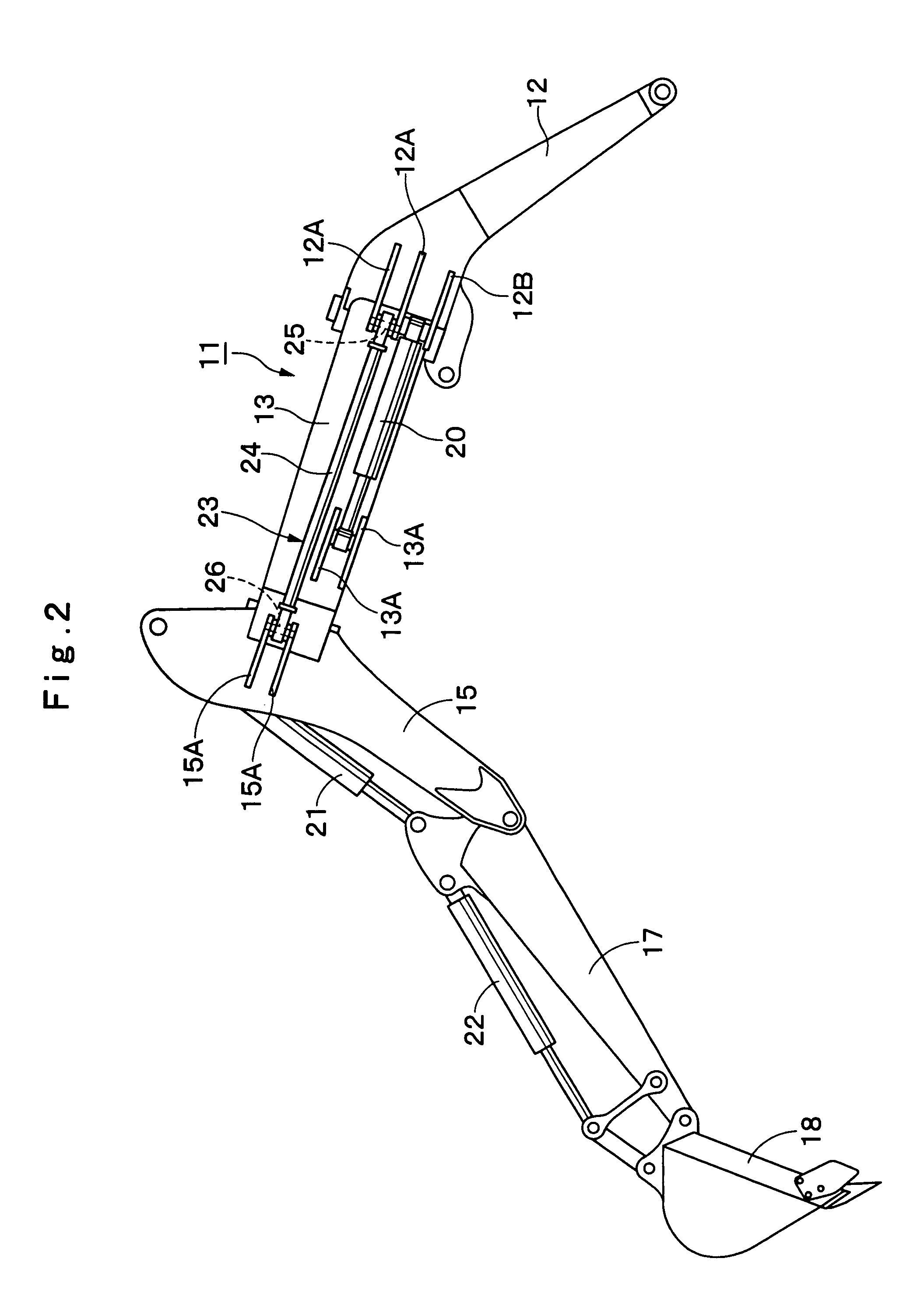
[0052]Reference numeral 11 denotes an offset boom type working mechanism that is provided on the right front of the upper revolving structure 3 for upward and downward rotational movement. As shown in FIGS. 2 and 3, the working mechanism 11 is constituted by a first boom 12, a second boom 13, a third boom 15, an arm 17, a bucket 18, cylinders 19, 20, 21 and 22 and a parallel support member 23, all of which will be described after.

[0053]Indicated at 12 is the first boom, the base of which is mounted on the upper revolving structure 3 a...

second embodiment

[0110]Furthermore, substantially in the same manner as the left chain 33 in the second embodiment, end bolts 44 are provided on both ends of the left wire cable 43. The end bolt 44 at the base end is fixed by a double nut 45 to the attachment 12D″ of the left bracket 12A″ of the first boom 12″. The end bolt 44 at the distal end is fixed to the attachment 15C″ of the left bracket 15A″ of the third boom 15″.

[0111]Reference numeral 46 denotes a right wire cable provided on the right side of the second boom 13. The right wire cable 46, substantially in the same manner as the left wire cable 43, is formed by a general-purpose metal wire cable for which end bolts 47 are provided at both ends.

[0112]Substantially in the same manner as the right chain 36 in the second embodiment, these end bolts 47 are fixed by double nuts 48 to the attachment 12D″ of the right bracket 12C″ of the first boom 12″ and to the attachment 15C″ of the right bracket 15B″ of the third boom 15″. When the second boom ...

eighth embodiment

[0140]the present invention is shown in FIGS. 17 and 18. The feature of the eighth embodiment is that the present invention is applied for a working mechanism having a third boom that is shorter than the one in the first embodiment. In this embodiment, the same reference numerals as are used in the first embodiment are employed to denote corresponding components, and no further explanation for them will be given.

[0141]Designated at 91 is a working mechanism mounted on an offset boom type hydraulic excavator. As shown in FIGS. 17 and 18, the working mechanism 91 is constituted by a first boom 12, a second boom 13, an arm 17, a bucket 18, cylinders 19, 20, 21′ and 22, and a parallel support member 23, all of which are substantially the same as those in the first embodiment, and an arm support member 92 that will be described after.

[0142]Indicated at 92 is an arm support member that constitutes the third boom of the working mechanism 91. By welding a plural number of steel plates, the ...


PUM


Abstract

A parallel support member is constituted by a pair of links that are respectively arranged on the left and right sides of a second boom. These links are connected between a first boom and a third boom. Thus, the second boom is moved to the left or right side by an offset cylinder. In this case, when one of the links pulls the third boom, the third boom, an arm, and a bucket can be moved toward the left or right side of a vehicle body to be parallel to the first boom. At this time, the links accept a force exerted in the pulling direction, but need not receive a force exerted in the compression direction, so that the cross sectional areas, the weights of these links can be reduced.

Description

TECHNICAL FIELD[0001]This invention relates to a working mechanism for a construction machine that is appropriate, for example, for an offset boom type hydraulic excavator.BACKGROUND ART[0002]Generally, there is an example common working mechanism for construction machines, part of which is moved (offset), in parallel, to the left or right side of the vehicle body. Such a working mechanism is employed for offset boom type hydraulic excavators, etc. (e.g., Japanese Patent Laid-Open No. 2003-96810 and No. 2001-317076).[0003]According to these prior arts, this type of working mechanism for a hydraulic excavator is constituted by three booms, i.e., first, second and third booms, and the first boom is mounted on the vehicle body of the hydraulic excavator as to be rotatable to the upper and lower sides. Further, the second boom is mounted on the distal end of the first boom as to be swingable to the left and right sides, and the third boom is mounted on the distal end of the second boom ...

Claims


Application Information

Patent Timeline
Patent Type & Authority Patents(United States)
IPC IPC(8): E02F3/38
CPCE02F3/301E02F3/307E02F3/325E02F3/32
Inventor GOKITA, OSAMU
Owner NIHON KENKI CO LTD
Why Eureka
Try Eureka