Protective Cover for a Hand-Held Cut-Off Machine

a protection cover and cut-off machine technology, which is applied in the direction of manufacturing tools, working accessories, and portable power-driven tools, can solve the problems of brittle material being bent, strong vibrations acting on the bracket, and overload of materials, and achieves the effect of reducing the weight of the cut-off machine, satisfying the temperature resistance of the bracket, and simple configuration

Active Publication Date: 2009-01-15
ANDREAS STIHL AG & CO KG
View PDF9 Cites 7 Cited by
  • Summary
  • Abstract
  • Description
  • Claims
  • Application Information

AI Technical Summary

Benefits of technology

[0011]Advantageously, one conduit section of the supply conduit passes through the bracket. A simple configuration of the protective cover results when the bracket has two legs and each leg has a spray nozzle arranged there at and when the conduit section passing through the bracket completely extends within the interior of the bracket and connects the two spray nozzles with one another. An additional connecting conduit of the two spray nozzles can thus be eliminated. Advantageously, the receptacle is an opening and the locking projection is provided on a hollow pin in which the spray nozzle is secured. The spray nozzle can supply cooling liquid through the opening to the cutting disc. The opening thus serves as a securing means for the locking projection of the bracket and as a passage for the cooling liquid. In this way, a simple configuration of the protective cover is provided.
[0012]Advantageously, the bracket has a support section that is arranged in the locked position on the outer circumference of the protective cover. In this way, the rotational position of the bracket on the outer circumference of the protective cover can be determined in a simple way. Expediently, the support section in the locked position is secured by a locking device on the circumference of the protective cover. Accordingly, in a simple way the position of the bracket can be secured wherein the bracket advantageously is locked at both ends and on the circumference of the protective cover so that a three-point support action for the bracket is provided. Expediently, the bracket is secured in the locked position by a securing means. The securing means is advantageously a securing screw. In this way, even at strong vibrations of the protective cover it is ensured that the bracket cannot become detached accidentally.
[0013]In order to achieve a minimal weight of the cut-off machine, it is provided that the protective cover is comprised of magnesium. The protective cover is advantageously produced by magnesium die casting. The bracket is comprised advantageously of fiberglass-reinforced plastic material. In particular, the bracket is comprised of fiberglass-reinforced polyphthalamide. In this way, a satisfactory temperature resistance of the bracket and at the same time a satisfactory strength can be achieved. The embodiment made from plastic material moreover provides a minimal weight of the bracket.

Problems solved by technology

Moreover in operation strong vibrations act on the bracket.
When releasing the bracket from the locking means, this brittle material must be bent.
This can cause overload of the material and thus breakage of the bracket.

Method used


Image

  • Protective Cover for a Hand-Held Cut-Off Machine
  • Protective Cover for a Hand-Held Cut-Off Machine
  • Protective Cover for a Hand-Held Cut-Off Machine

Examples


Embodiment Construction

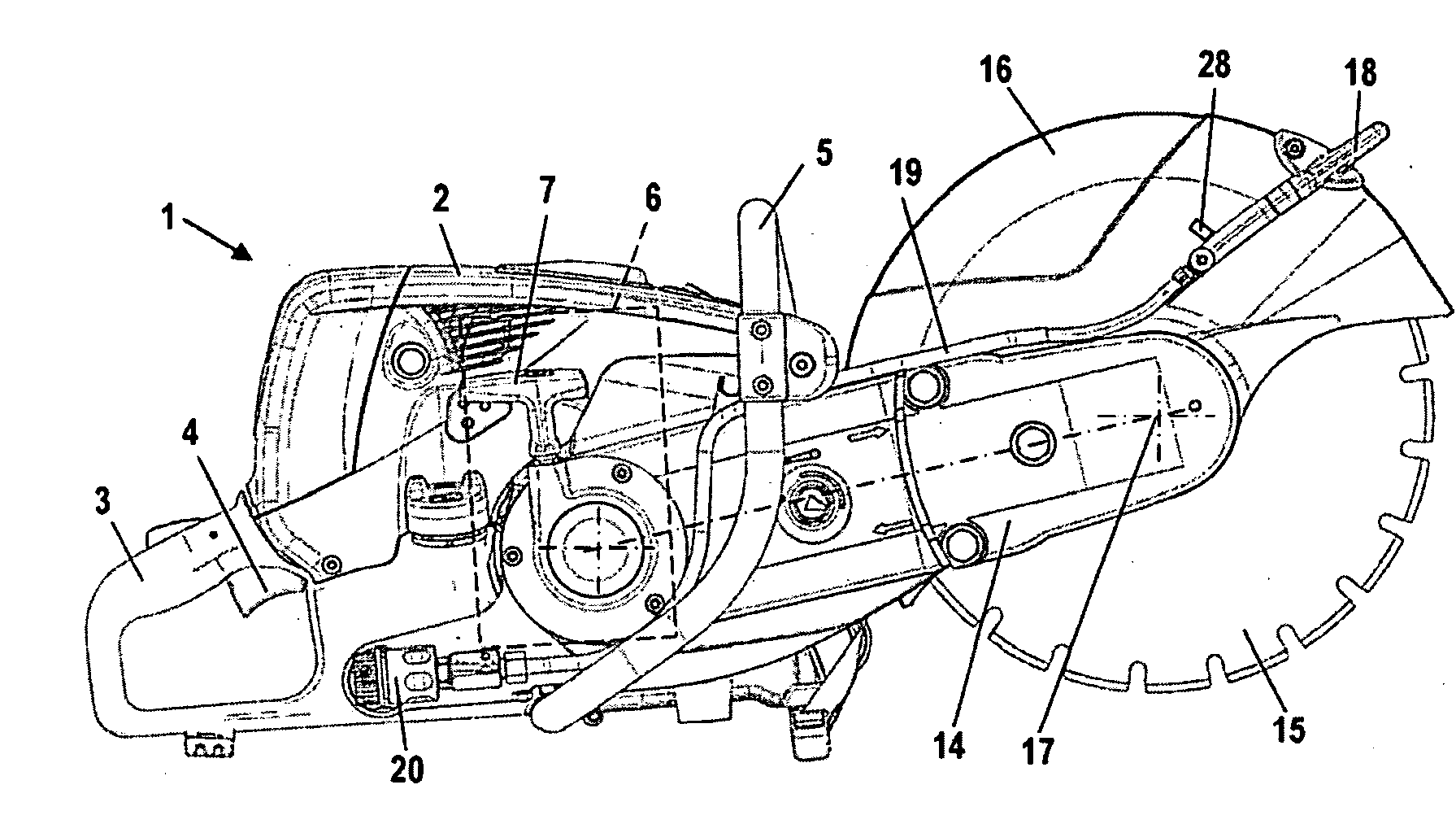
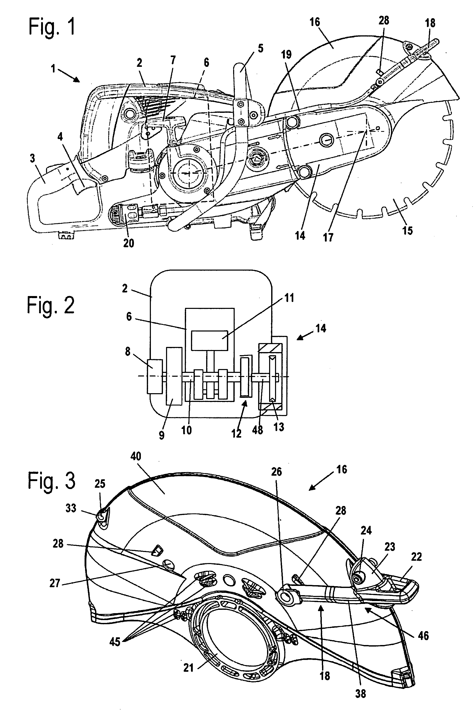
[0025]The cut-off machine 1 illustrated in FIG. 1 is a hand-held portable cut-off machine. The cut-off machine 1 can also be secured on a guide carriage. The cut-off machine 1 has a housing 2 on which a rear handle 3 is arranged. On the rear handle 3 a throttle lever 4 is pivotably arranged for operating a drive motor 6 arranged in the housing 2. On the housing 2, on the side facing away from the rear handle, there is a grip pipe 5 that extends across the housing 2. A starter handle 7 of a starter device 8 of the drive motor 6, shown in FIG. 2, projects from the housing 2. On the housing 2 an extension arm 14 is secured that projects forwardly; on it a cutting disc 15 is supported so as to rotate about axis of rotation 17. The cut-off disc 15 is surrounded about part of its circumference by a protective cover 16. The protective cover 16 can extend, for example, about half the circumference of the cutting disc 15.

[0026]A supply conduit 19 is provided on the cut-off machine 1 for supp...


PUM

PropertyMeasurementUnit
angleaaaaaaaaaa
heightaaaaaaaaaa
outer circumferenceaaaaaaaaaa

Abstract

A protective cover of a hand-held cut-off machine has a bracket that is secured on the exterior side of the protective cover. The bracket is locked in at least one locked position with at least one locking projection in at least one receptacle of the protective cover. The bracket is releasable from the locked position by a movement of the bracket in the release direction. A simple release of the bracket can be achieved in that the protective cover has means that move the locking projection upon movement of the bracket in the release direction at least partially out of the receptacle.

Description

BACKGROUND OF THE INVENTION[0001]The invention concerns a protective cover of a hand-held cut-off machine wherein the protective cover comprises a bracket secured on the exterior side of the protective cover. The bracket in at least one locked position is locked with at least one locking projection in at least one receptacle of the protective cover. The bracket, by a movement of the bracket in a release direction, is releasable from the locked position.[0002]U.S. 2006 / 0128289 A1 discloses a protective cover of a hand-held cut-off machine that is provided with a bracket. The bracket serves in particular for supplying a liquid, such as water, to the cutting disc. The liquid (water) supplied through the hollow bracket serves primarily for binding dust produced during cutting as well as for cooling and lubricating the cutting disc. The protective cover can be secured on the extension arm of the cut-off machine in different positions, i.e., on both sides of the extension arm of the cut-o...

Claims


Application Information

Patent Timeline
Patent Type & Authority Applications(United States)
IPC IPC(8): B27B9/00B25F5/00B23D45/16
CPCB28D7/02B24B55/052B24B27/08B24B55/05B28D7/00
Inventor AMEND, HELMARHOFFMANN, JOACHIMBUCK, ERNST
Owner ANDREAS STIHL AG & CO KG
Why Eureka
Try Eureka