Thin film magnetic head, method of manufacturing the same, and magnetic recording apparatus

Inactive Publication Date: 2006-08-10
SAE MAGNETICS (HK) LTD
View PDF5 Cites 6 Cited by
  • Summary
  • Abstract
  • Description
  • Claims
  • Application Information

AI Technical Summary

Benefits of technology

[0027] In the thin film magnetic head and the magnetic recording apparatus according to an embodiment of the invention, the magnetic pole in the magnetic pole layer is constructed so as to have the stacking structure in which a first magnetic pole portion having a relatively low first saturated magnetic flux density is positioned on the opposite side in the medium travel direction, and a second magnetic pole portion having a relatively high second saturated magnetic flux density is positioned in the medium travel direction. The exposed surface has a planar shape in which a width of the second edge is larger than a width of the first edge, and is equal to or larger than a width of the exposed surface at an arbitrary intermediate position between the first and the second edges. In particular, a height at a center position in the second exposed surface area is larger than a height of the second exposed surface area at an arbitrary peripheral position around the center position. Based on the structural features, the strength of the perpendicular magnetic field is assured in an information recording operation and the width of a record

Problems solved by technology

It is, however, difficult to satisfy both of assurance of the strength of a perpendicular magnetic field and reduction in the recording track width in a traditional thin film magnetic head of the perpendicular recording method.
Consequent

Method used


Image

  • Thin film magnetic head, method of manufacturing the same, and magnetic recording apparatus
  • Thin film magnetic head, method of manufacturing the same, and magnetic recording apparatus
  • Thin film magnetic head, method of manufacturing the same, and magnetic recording apparatus

Examples


Embodiment Construction

[0047] Embodiments of the invention will be described in detail hereinbelow with reference to the drawings.

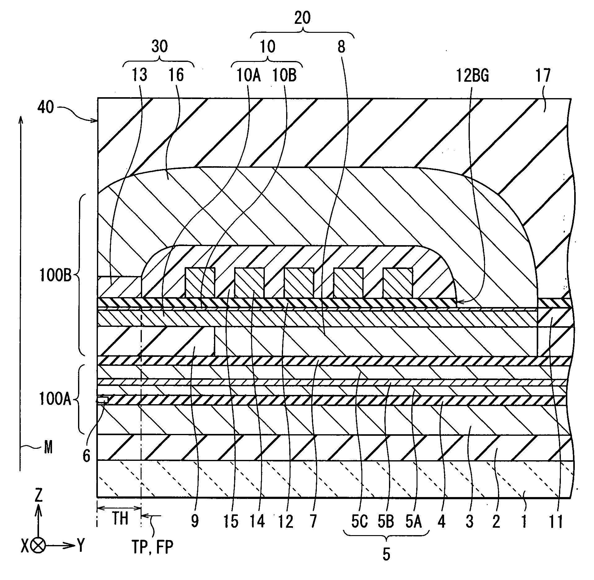
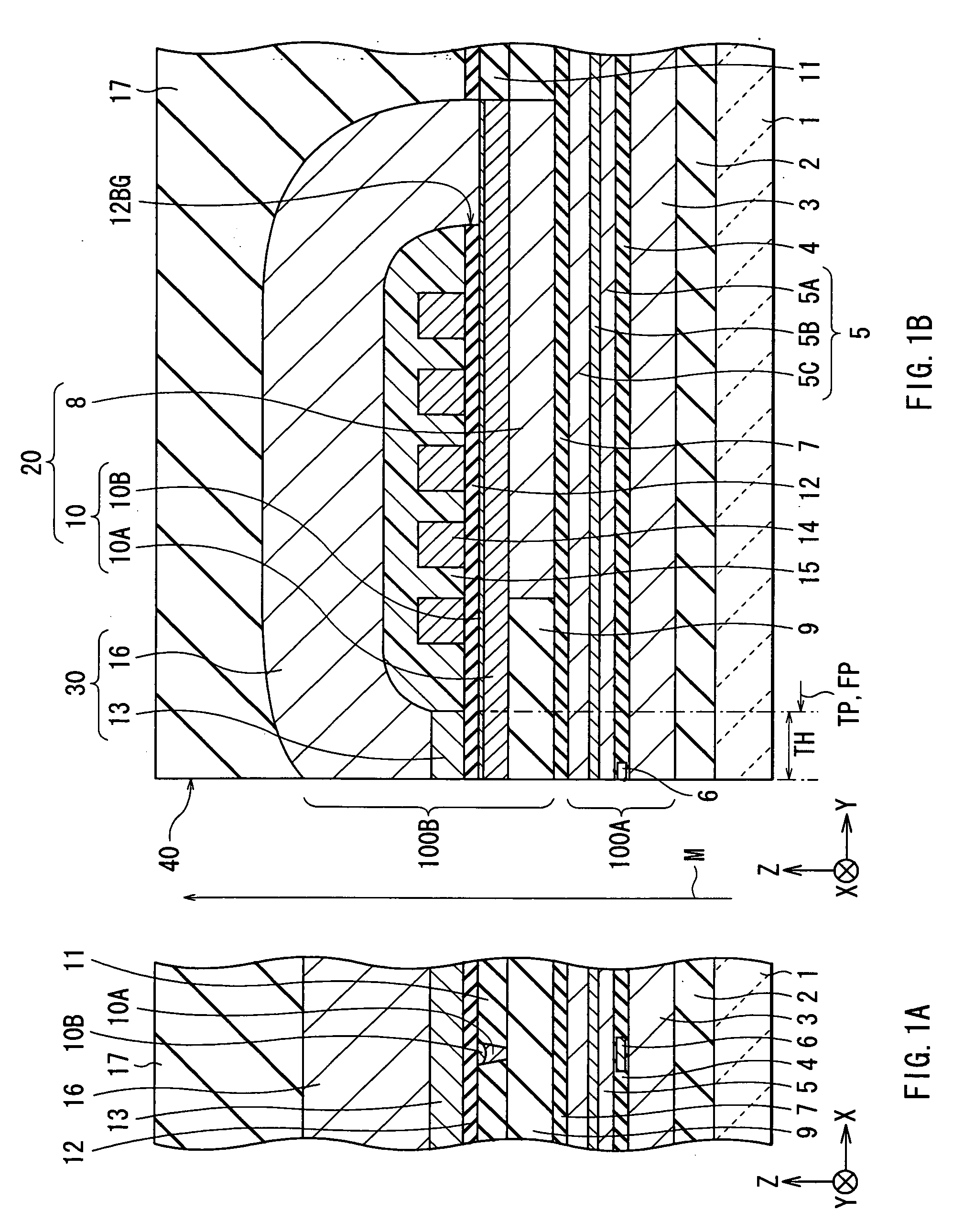
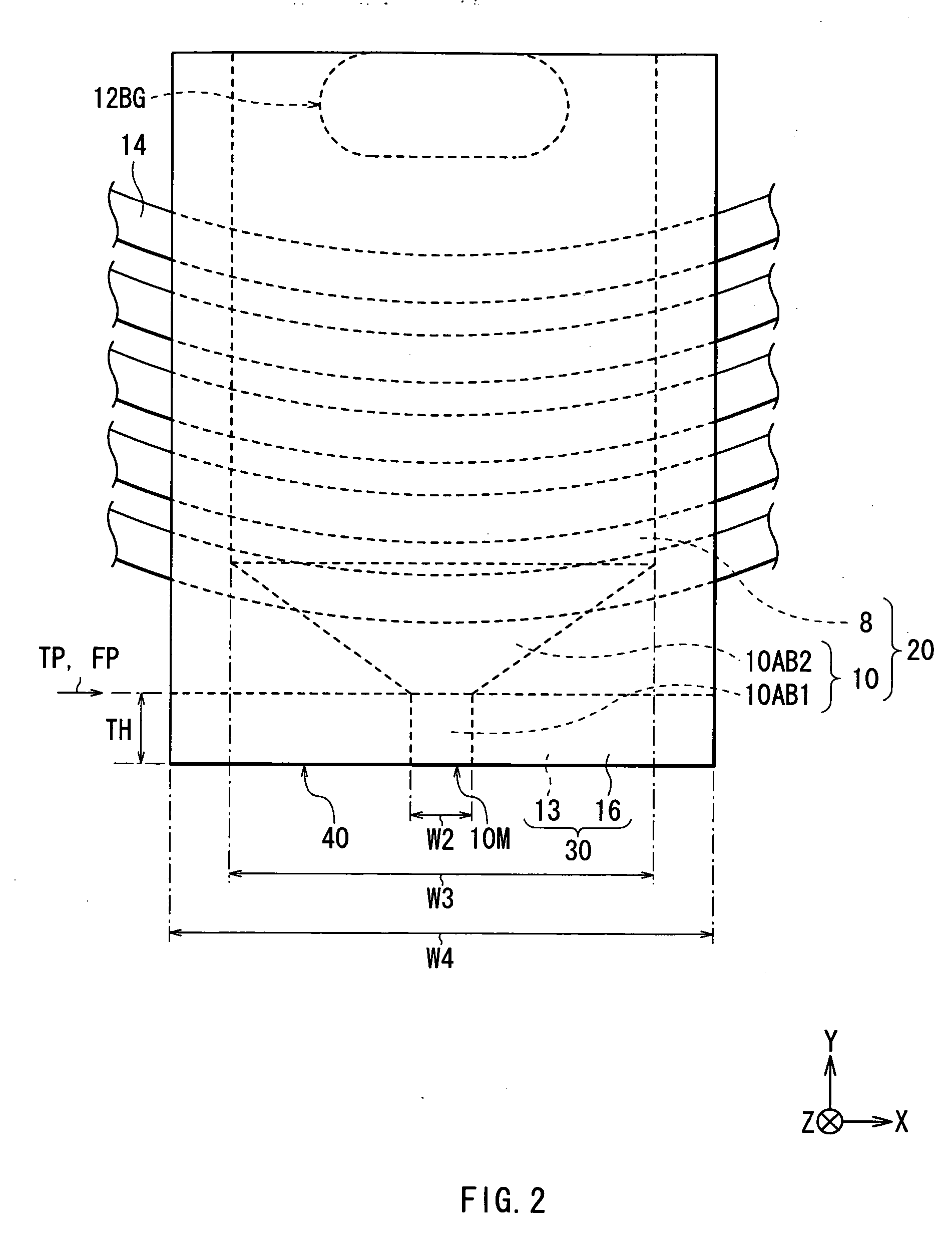
[0048] First, the configuration of a thin film magnetic head according to an embodiment of the invention will be described with reference to FIGS. 1A and 1B to FIG. 4. FIGS. 1A and 1B to FIG. 4 show a configuration of a thin film magnetic head. FIGS. 1A and 1B show a general sectional configuration. FIG. 2 shows a planar configuration (a planar configuration seen from the Z-axis direction) of the main part in the thin film magnetic head. FIG. 3 shows an enlarged planar configuration (a planar configuration seen from the Y-axis direction) of an exposed surface 10M of a main magnetic pole layer 10. FIG. 4 shows an enlarged perspective configuration of the main magnetic pole layer 10. FIG. 1A shows a sectional configuration parallel to an air bearing surface40 (a sectional configuration along an XZ plane) and FIG. 1B shows a sectional configuration perpendicular to the air bearin...


PUM


Abstract

A main magnetic pole layer is constructed so as to have a stacking structure in which a lower main magnetic pole layer having relative low saturated magnetic flux density and an exposed surface area is positioned on a leading side, and an upper main magnetic pole layer having relative high saturated magnetic flux density and having an exposed surface area is positioned on a trailing side. The exposed surface of a main magnetic pole layer has a planar shape of a bilaterally-symmetrical inverted trapezoidal shape in which a width of an upper edge is larger than a width of a lower edge and is equal to or larger than a width of the exposed surface of the main magnetic pole layer at an arbitrary intermediate position between the lower edge and the upper edge. In particular, a height at a center position in the exposed surface area in the upper main magnetic pole layer is larger than a height in the exposed surface area in an arbitrary peripheral position around the center point.

Description

BACKGROUND OF THE INVENTION [0001] 1. Field of the Invention [0002] The present invention relates to a thin film magnetic head having at least an inductive magnetic transducer for recording, a method of manufacturing the same, and a magnetic recording apparatus in which a thin film magnetic head is mounted. [0003] 2. Description of the Related Art [0004] In recent years, in association with improvement in areal density of a magnetic recording medium (hereinbelow, simply called “recording medium”) such as a hard disk, improvement in the performance of a thin film magnetic head to be mounted on a magnetic recording apparatus such as a hard disk drive (HDD) is demanded. Examples of known recording methods of a thin film magnetic head are a longitudinal recording method in which the orientation of a signal magnetic field is set to an in-plane direction (longitudinal direction) of a recording medium and a perpendicular recording method in which the orientation of a signal magnetic field ...

Claims


Application Information

Patent Timeline
IPC IPC(8): G11B5/147
CPCG11B5/1278G11B5/3116G11B5/3163
Inventor MATONO, NAOTO
Owner SAE MAGNETICS (HK) LTD
Why Eureka
Try Eureka