Solid oxide fuel cell and manufacturing method and manufacturing apparatus for same

a manufacturing method and fuel cell technology, applied in the field of solid oxide fuel cells, can solve the problems of increasing the number of manufacturing processes, increasing the cost of manufacturing, and deteriorating of the cells, and achieve the effects of reducing the risk of cracking in the ceramic adhesive layer at the cell joint portions, reducing manufacturing time, and small volum

Inactive Publication Date: 2017-01-10
TOTO LTD
View PDF2 Cites 0 Cited by
  • Summary
  • Abstract
  • Description
  • Claims
  • Application Information

AI Technical Summary

Benefits of technology

[0021]In the invention thus constituted, ceramic adhesive applied in the adhesive application step is hardened in the workable hardening step. After the end of the workable hardening step, the ceramic adhesive is hardened to the point that the next manufacturing process can be implemented, but cracks can develop when the solid oxide fuel cell apparatus is operated after being assembled. Thus the next manufacturing process can be implemented in the workable hardening step, but when the temperature is raised for approximately two hours to the electrical generation temperature of 600° C. or greater in the startup procedure when transitioning to an electrical generation operation, a large amount of solvent remains, and in this state sudden volumetric expansion and sudden vaporization of the solvent due to sudden heating in the startup procedure causes cracking, but since it is sufficient to harden only enough so that work in the next step can be performed, the drying and hardening time can be shortened and the transition to the next step can be made in a short time. Also, because drying and hardening takes this form, vaporization of solvent is slow, and there is no risk of cracking. This is a skillful use of the characteristics of ceramic adhesive. Specifically, it was found that if the purpose is only to obtain a hardened state sufficient for the solid oxide fuel cell to perform work, ceramic adhesive can perform this in an extremely short time, whereas if the purpose is to assure strength, prevent cracking, and secure airtightness, the drying and hardening time must be extremely lengthened.
[0056]The invention thus constituted executes a workable hardening step on cell joint portions, then a solvent elimination and hardening step on joint portions other than fuel cells, and a solvent elimination and hardening step on dried ceramic adhesive. As a result, multiple iterations of the workable hardening step can be applied to the cell joint portions, while at the same time the solvent elimination and hardening step can be applied to multiple joint portions, and the risk of cracking of the ceramic adhesive in cell joint portions can be extraordinarily reduced.

Problems solved by technology

However, when securing airtightness by injecting glass in paste form into joint portions after mechanically affixing constituent members with bolts or the like, the problem arises that two steps are required for a single location, raising costs as the number of manufacturing processes increases.
In addition, when constituent members are affixed using bolts inside a fuel cell module, chrome components vaporize from the bolts when exposed to high temperatures, causing chrome poisoning of the fuel cells leading to degradation of the cells.
The problem can also arise that when sealing is done using glass in order to achieve airtightness at joining portions, boron vaporizes from the glass and causes degradation of the fuel cells by adhering thereto.
The problem for conventional joints using ceramic adhesive, however, has been that a reliable seal could not be made between constituent members at the same time that constituent members are affixed to one another.
That is, because solvent such as water vaporize when a ceramic adhesive is dried after being applied, their volume shrinks, and unless this shrinkage is skillfully controlled, peeling and excessive cracking associated with shrinkage occurs in the ceramic adhesive layer after hardening.
When such peeling or cracking does occur in the ceramic adhesive layer, sufficient sealing properties cannot be secured in those joint portions even though sufficient adhesion strength may be obtained between constituent members.
However, when a ceramic adhesive layer is coated with glass, the number of manufacturing processes increases and the problem of boron evaporation from the glass occurs, so there is no advantage to using the ceramic adhesive.

Method used


Image

  • Solid oxide fuel cell and manufacturing method and manufacturing apparatus for same
  • Solid oxide fuel cell and manufacturing method and manufacturing apparatus for same
  • Solid oxide fuel cell and manufacturing method and manufacturing apparatus for same

Examples


Embodiment Construction

[0088]Next, referring to the attached drawings, we discuss a solid oxide fuel cell apparatus (SOFC) according to an embodiment of the present invention.

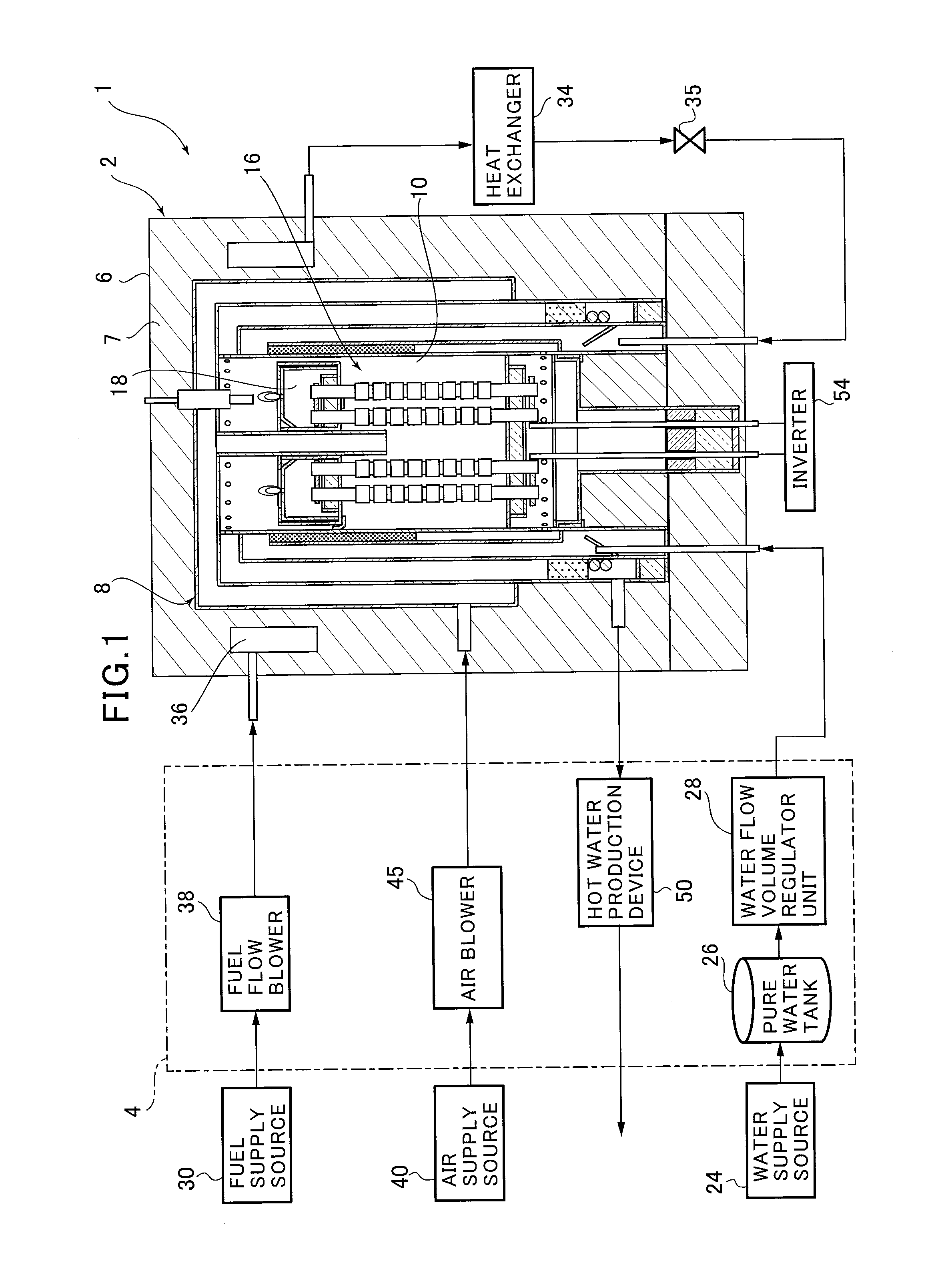
[0089]FIG. 1 is an overview diagram showing a solid oxide fuel cell (SOFC) apparatus according to an embodiment of the present invention. As shown in FIG. 1, the solid oxide fuel cell (SOFC) apparatus of this embodiment of the present invention is furnished with a fuel cell module 2 and an auxiliary unit 4.

[0090]Fuel cell module 2 comprises a fuel cell housing container 8; is formed within this housing 6, mediated by thermal insulation 7. A generating chamber 10 is formed on the interior of this fuel cell housing container 8; multiple fuel cells 16 are concentrically disposed within this generating chamber 10, and the generating reaction between fuel gas and air, which is the oxidizing gas, is carried out by these fuel cells 16.

[0091]An exhaust collection chamber 18 is attached to the top end of each individual fuel cell 16. Residual...


PUM

PropertyMeasurementUnit
temperatureaaaaaaaaaa
temperaturesaaaaaaaaaa

Abstract

The present invention provides a novel manufacturing method for a solid oxide fuel cell apparatus in which members of the apparatus are joined together with an adhesive, such as a ceramic adhesive. The method implements first and second types of drying and hardening steps. The first type of step may be called a workable hardening step and gives an assembly of members in the solid oxide fuel cell apparatus structural rigidity to go through assembling of the solid oxide fuel cell apparatus. The second type of step may be called a solvent elimination and hardening step and gives the assembled members property to withstand the operation temperature of the solid fuel oxide cell apparatus. The first type of step is performed at a first temperature lower than a second temperature at which the second type of step is performed. The second type of step is performed only after the first type of step is performed at multiple times.

Description

RELATED APPLICATIONS[0001]This application claims priority under 35 U.S.C. §119 to Japanese Patent Application Nos. 2013-135080 filed on Jun. 27, 2013 and 2013-135081 filed on Jun. 27, 2013, the entire contents of which are hereby incorporated by reference.BACKGROUND OF THE INVENTION[0002]1. Technical Field[0003]The invention pertains to a solid oxide fuel cell, and more particularly to a solid oxide fuel cell and manufacturing method and manufacturing apparatus for same.[0004]2. Background Art[0005]Solid oxide fuel cells (“SOFCs” below) are fuel cells which operate at a relatively high temperature in which, using an oxide ion-conducting solid electrolyte as electrolyte, with electrodes attached to both sides thereof, fuel gas is supplied to one side thereof and oxidant gas (air, oxygen, or the like) is supplied to the other side thereof.[0006]A fuel flow path for supplying fuel to fuel cells, and an oxidant gas flow path or the like for supplying oxidant gas such as air, are built ...

Claims


Application Information

Patent Timeline
Patent Type & Authority Patents(United States)
IPC IPC(8): H01M8/24H01M8/12
CPCH01M8/12H01M2008/1293Y02E60/521Y02E60/525Y02P70/56H01M8/0271H01M8/0282H01M8/0286H01M8/04089H01M8/0612H01M8/2465H01M8/249Y02E60/50Y02P70/50
Inventor ISAKA, NOBUOWATANABE, NAOKITANAKA, SHUHEIHOSHIKO, TAKUYASATO, MASAKIOKAMOTO, OSAMUANDO, SHIGERUFURUYA, SEIKIMOMIYAMA, YUTAKAHAYAMA, KIYOSHI
Owner TOTO LTD
Why Eureka
Try Eureka