Recording tape cartridge

a tape cartridge and tape technology, applied in the field of recording tape cartridges, can solve the problems of affecting the appearance of the cartridge, affecting so as to improve the rigidity of the case, and improve the quality of the cartridge.

Inactive Publication Date: 2005-12-27
FUJIFILM HLDG CORP +1
View PDF7 Cites 0 Cited by
  • Summary
  • Abstract
  • Description
  • Claims
  • Application Information

AI Technical Summary

Benefits of technology

[0018]Thus, because the annular protruding portion is protrudingly provided at the inner side of the reel area ribs, rigidity of the case can be improved. Moreover, because the portions that would be thinner because of the reference surfaces are made thicker by the annular protruding portion and the thickening portions, differences in thickness with respect to positions surrounding the reference surfaces, that is, the differences in thickness between positions at the reference surfaces and positions surrounding the reference surfaces, can be made smaller, and variations in pressure during molding can be made smaller. Consequently, sinking after forming and/or flow lines and the like are less likely to occur at the perip

Problems solved by technology

As a result, sinking after forming, and flow lines and the like can occur.
Moreover, mold transcription is variable,

Method used


Image

  • Recording tape cartridge
  • Recording tape cartridge
  • Recording tape cartridge

Examples


Embodiment Construction

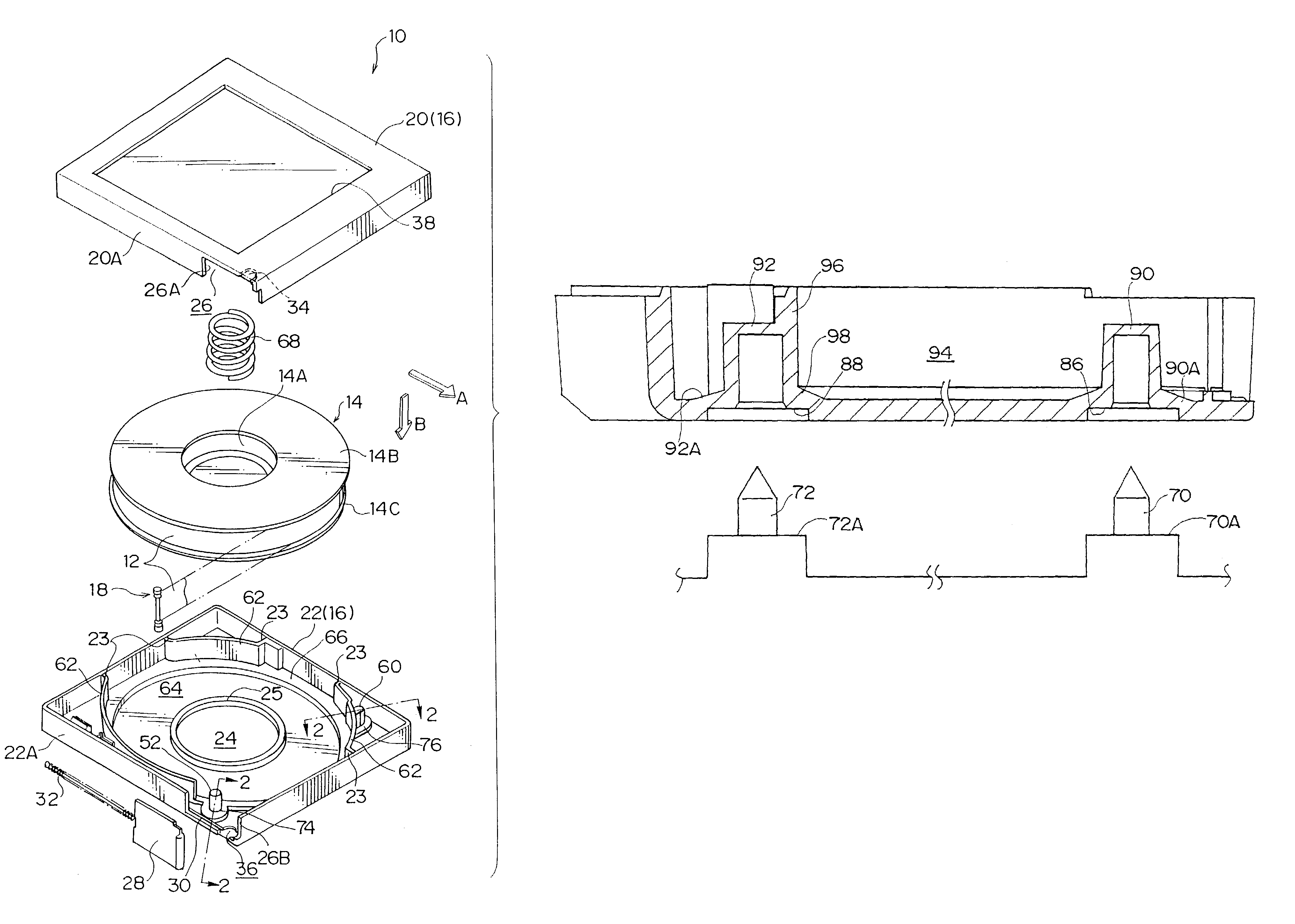
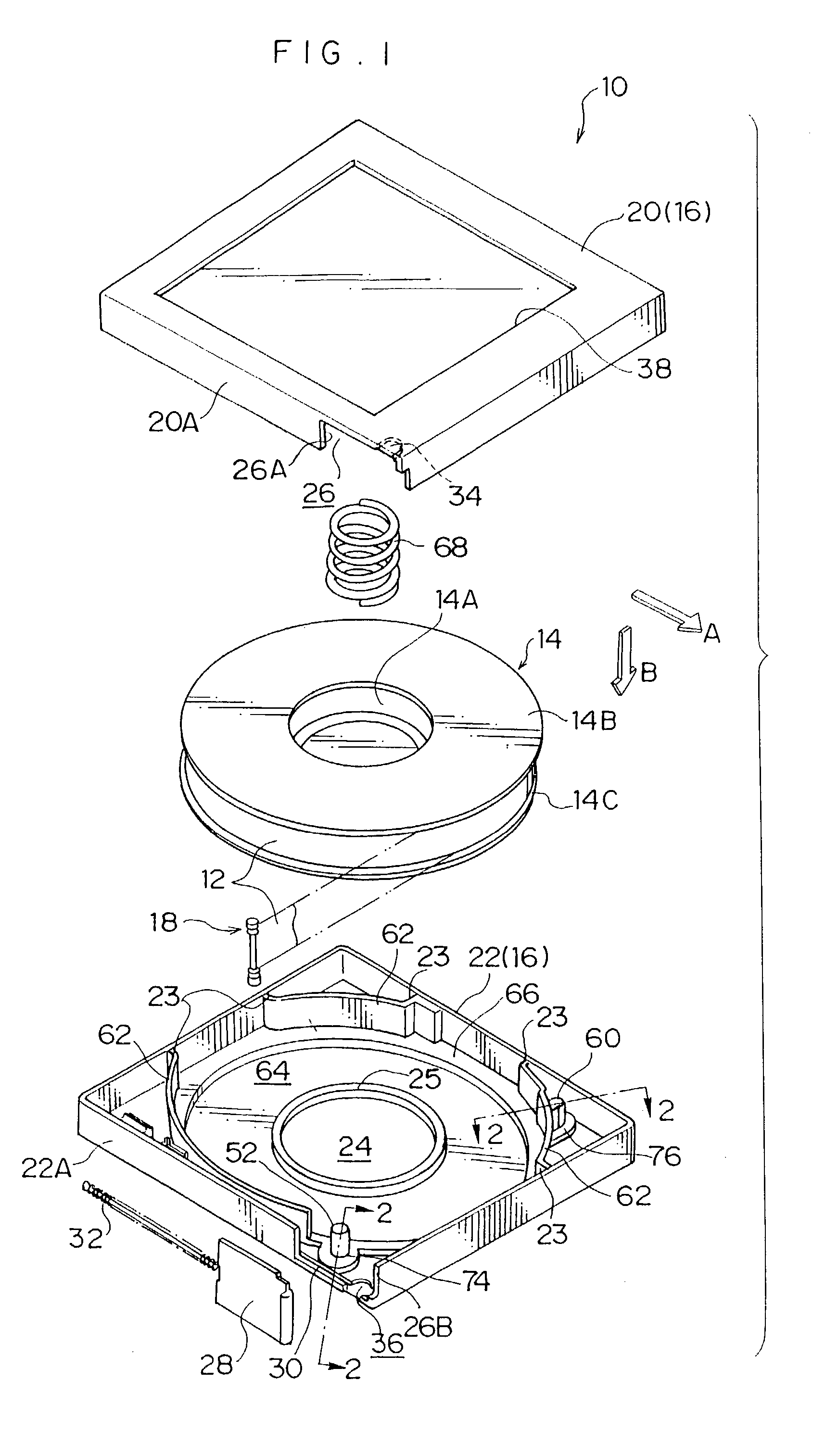
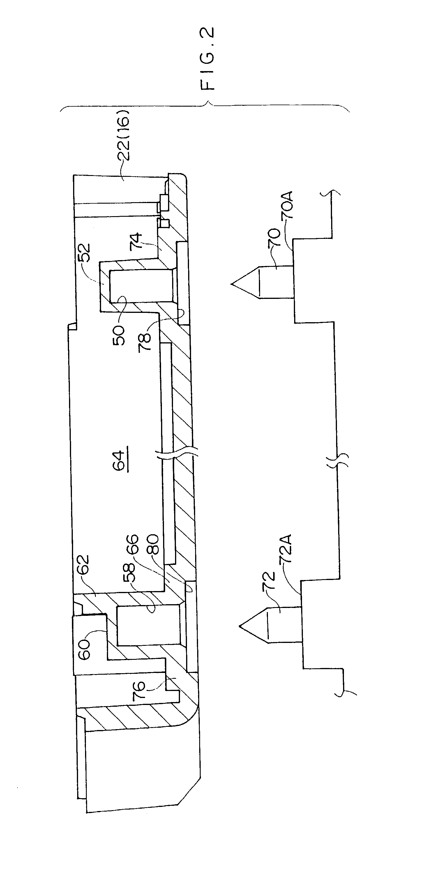
[0027]A recording tape cartridge 10 relating to an embodiment of the present invention will be described on the basis of FIGS. 1 to 3. For convenience of explanation, a direction of loading the recording tape cartridge 10 into a drive device (the direction of an arrow A) is taken to be a forward direction, and the direction of an arrow B is taken to be a downward direction. Front, back, left, right, up and down are expressed with reference to a case of viewing in the direction of arrow A.

[0028]As shown in FIG. 1, the recording tape cartridge 10 is structured to rotatably accommodate a single reel 14 in a case 16. A magnetic tape 12, which serves as a recording tape which is an information recording / replaying medium, is wound on the reel 14. The case 16 is substantially rectangular in plan view.

[0029]At the reel 14, an upper flange 14B and a lower flange 14C are coaxially provided at respective upper and lower ends of a substantially cylindrical reel hub 14A. The reel 14 is formed su...


PUM


Abstract

Structure of a lower case that reinforces a recording tape cartridge. At an inner side of the lower case, an annular projecting portion is provided along and at an inner side of a reel area rib that demarcates a reel area, raising stiffness of the case. At a periphery of a hole for positioning, which is formed in an outer face of the lower case, a recessed surface, which provides a height direction reference surface, is formed. At the inner side of the lower case, a boss is formed in correspondence to the hole for positioning. The boss is located along an outer face of the reel area rib. A thickness-enhancing portion is formed at the periphery of a base portion of the boss. Thus, thickness at the reference surface, that is, the recessed surface, is substantially the same as thickness at portions therearound.

Description

BACKGROUND OF THE INVENTION[0001]1. Field of the Invention[0002]The present invention relates to a recording tape cartridge which accommodates a reel on which a recording tape such as a magnetic tape or the like is wound, the recording tape cartridge being loaded at a drive device when in use.[0003]2. Description of the Related Art[0004]Recording tapes such as magnetic tapes and the like are used as recording media for saving data (information) for computers and the like, and for audio use, video use and the like. In order to prevent damage to a recording surface of such a recording tape, due to adherence of dust or the like to the recording surface, finger contact or the like, such a recording tape is employed in a recording tape cartridge. In this recording cartridge, the recording tape is wound onto a reel and the reel is rotatably accommodated in a case formed of resin.[0005]“Single reel cartridges”, in which a recording tape wound onto a single reel is accommodated in a case (t...

Claims


Application Information

Patent Timeline
IPC IPC(8): G11B23/087G11B23/107
CPCG11B23/107
Inventor HIRAGUCHI, KAZUO
Owner FUJIFILM HLDG CORP
Why Eureka
Try Eureka