Air filter for a scoop

a technology of air filter and scoop, which is applied in the field of air filters, can solve the problems of air filter reducing the air velocity through the inlet opening of the scoop, and achieve the effects of increasing the size of the air filter, and reducing the air velocity

Active Publication Date: 2008-11-18
K&N ENGINEERING INC
View PDF10 Cites 20 Cited by
  • Summary
  • Abstract
  • Description
  • Claims
  • Application Information

AI Technical Summary

Benefits of technology

[0007]By placing the air filter within the scoop and adjacent to the inlet opening of the scoop, the size of the air filter may be increased as compared to a traditional air filter which fits within the neck area of the scoop. As such, the surface area of the air filter may be increased to provide more air to the air intake system as compared to the traditional air filter. In addition, with the air filter mounted adjacent to the inlet opening of the scoop, the air filter may reduce the air velocity through the inlet opening of the scoop. By reducing the air velocity through the inlet opening of the scoop, the air filter minimizes the occurrence of air turbulence forming within the scoop, thereby increasing restrictions.
[0008]The air filter may also have an inner filtering body within the outer filtering body. The inner filtering body may be coupled to the outer filtering body along the base of the air filter. The inner filtering body may have a tip extending from the base of the air filter. The tip of the inner filtering body may be within the mouth of the outer filtering body to provide additional surface area to filter the air entering the mouth of the outer filtering body. The inner filtering body may also act as a boundary surface to guide the air flowing into the mouth towards the outer filtering body. The tip of the inner filtering body may also protrude from the mouth of the outer filtering body to increase the surface area of the inner filtering body and to allow the air in front of the inlet opening of the scoop to be drawn into the scoop. The tip protruding from the inlet opening of the scoop also improves the aerodynamics of the scoop because the protruding tip rounds off the inlet opening of the scoop.

Problems solved by technology

In addition, with the air filter mounted adjacent to the inlet opening of the scoop, the air filter may reduce the air velocity through the inlet opening of the scoop.

Method used


Image

  • Air filter for a scoop
  • Air filter for a scoop
  • Air filter for a scoop

Examples


Embodiment Construction

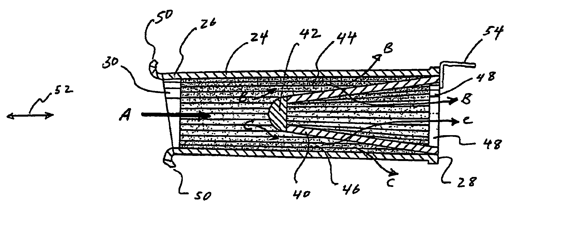
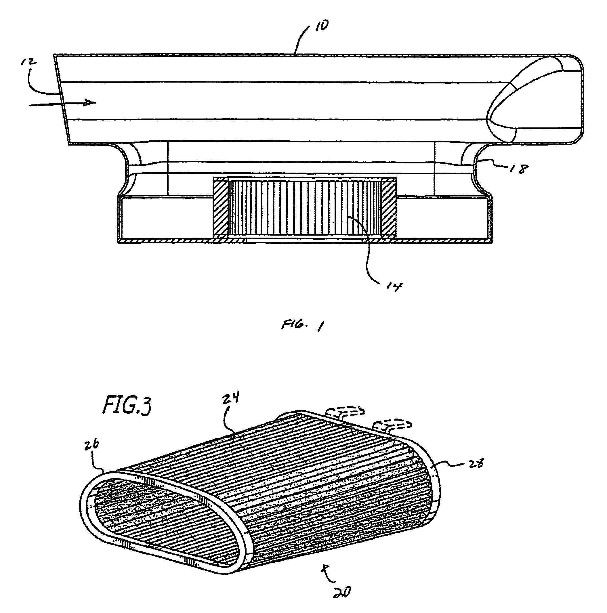
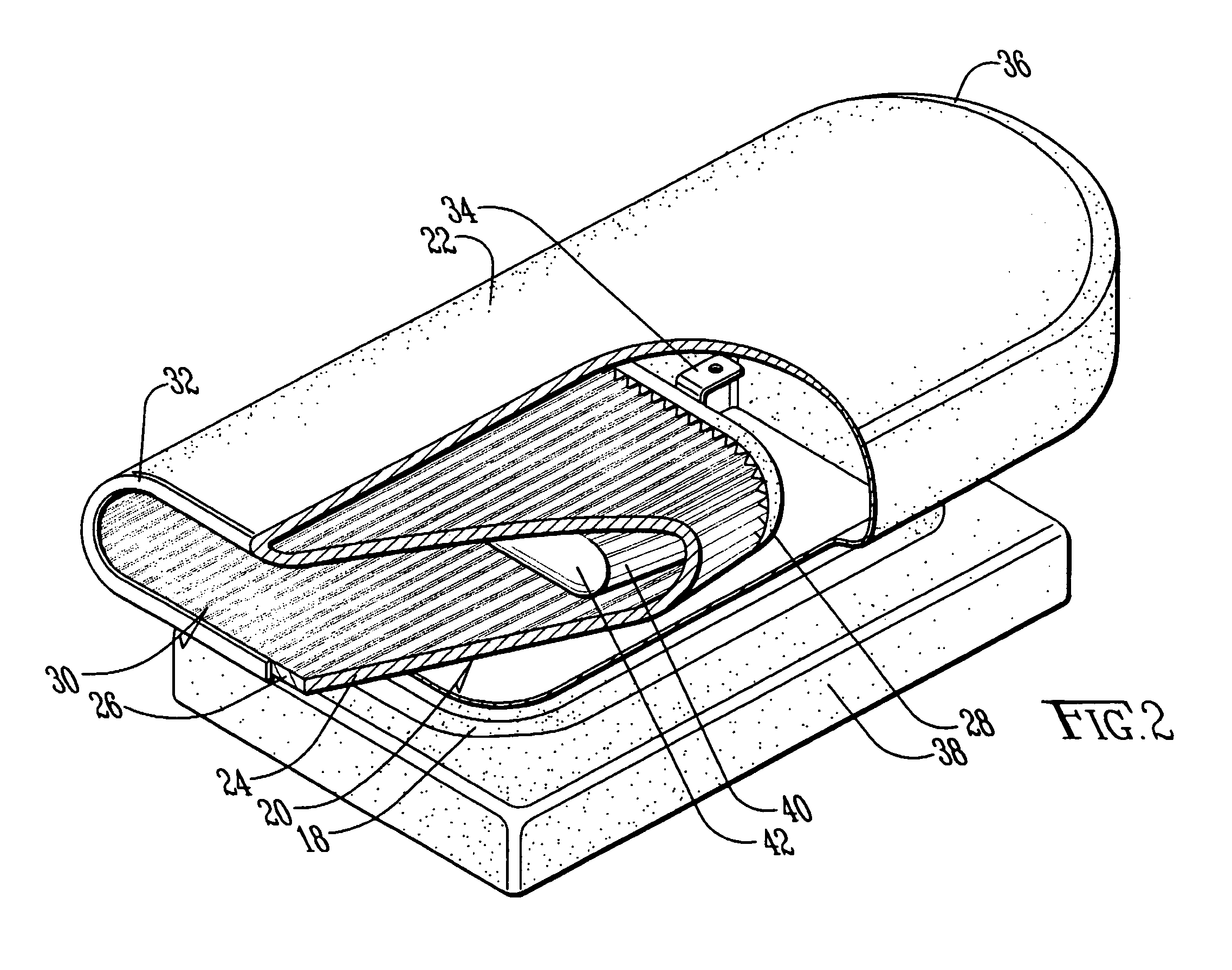
[0018]FIG. 2 is a perspective cutout view of an air filter 20 within a scoop 22 which is adapted to mount over an air intake system such as a carburetor, fuel injectors, throttle body, or the like of a vehicle. The air filter 20 has an outer filtering body 24 between a lip 26 and a base 28. The air filter 20 also has a mouth 30, defined by the lip 24, adapted to receive air therethrough to allow the outer filtering body 22 to filter the air and pass the filtered air to the air intake system located underneath the scoop 22. The scoop 22 has an inlet opening 32 to receive air substantially along a horizontal plane. The scoop 22 has a back end 36 that turns the flow of air about 90 degrees towards the air intake system located near the base 38 of the scoop 22. The lip 26 of the air filter 20 may be adapted to substantially conform with the circumference configuration of the inlet opening 32 of the scoop 22 so that a substantial portion of the air passing through the inlet opening 32 of...


PUM

PropertyMeasurementUnit
speedaaaaaaaaaa
lengthaaaaaaaaaa
circumferenceaaaaaaaaaa

Abstract

An air filter has an inner filtering body within an outer filtering body. The air filter is configured to fit inside a scoop and adjacent to the inlet opening of the scoop. By placing the air filter adjacent to the inlet opening of the scoop, the size of the air filter may be increased as compared to a traditional air filter which fits within the neck area of the scoop. As such, the surface area of the air filter may be increased to provide more air to an air intake system such as a carburetor, fuel injectors, throttle body, or the like, as compared the traditional air filter. The inner filtering body may be recessed inside or protrude from the outer filtering body. The inner filtering body may be coupled to the outer filtering body along the base of the air filter. The inner filtering body increases the surface area of the air filter so that more air may be provided to the air intake system of a vehicle.

Description

BACKGROUND OF THE INVENTION[0001]1. Field of the Invention[0002]This invention is directed to an air filter adapted to filter air passing through a scoop which is mounted over an air intake system such as a carburetor, fuel injector or throttle body of a vehicle.[0003]2. General Background and State of the Art[0004]FIG. 1 is a cross-sectional view of a scoop 10 designed to direct air to a traditional air filter 14 mounted over an air intake system of an engine such as a carburetor, fuel injector, throttle body or the like. Air enters through a front opening 12 of the scoop 10 which is filtered by the traditional air filter 14 before the filtered air is provided to the air intake system. The air filter 14 is mounted over the air intake system such that the air filter 14 fits within the neck area 18 of the scoop 10. The design of this scoop 10 is such that the size of the air filter 14 is limited by the space available near the neck area 18 of the scoop 10. In some applications, no fi...

Claims


Application Information

Patent Timeline
Patent Type & Authority Patents(United States)
IPC IPC(8): B01D50/00
CPCB01D46/0024B01D46/2403B01D2275/206B01D2275/207B01D46/521B01D46/64
Inventor FIELLO, JONATHAN RICHARDMILES, DAVID JAMESWILLIAMS, STEVE
Owner K&N ENGINEERING INC
Why Eureka
Try Eureka