Barrier rib structure of plasma display panel

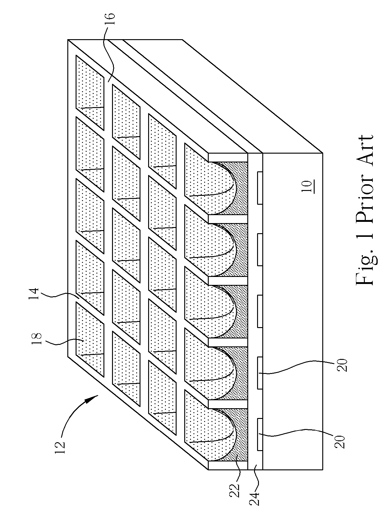
a plasma display panel and barrier rib technology, which is applied in the manufacture of electrode systems, electric discharge tubes/lamps, gas exhaustion means, etc., can solve the problems of reducing the overall brightness of the pdps, and reducing the speed of gas exhaust and incomplete exhaust, so as to effectively reduce the interference between electrical discharge space and prolong the life of the plasma display panel. , to prevent the global breakdown phenomenon, the effect o

Inactive Publication Date: 2008-11-18
CHUNGHWA PICTURE TUBES LTD
View PDF10 Cites 6 Cited by
  • Summary
  • Abstract
  • Description
  • Claims
  • Application Information

AI Technical Summary

Benefits of technology

[0011]By utilizing a double blockade structure and vertical barrier ribs to form an electrical discharge space, the present invention is able to provide enough exhausting passage to improve problems such as slow exhaust, incomplete exhaust, difference in the degree of purity of the gas being sucked inside, and electrical discharge instability, thereby extending the life expectancy of the plasma display panel. Moreover, the double blockade structure of the present invention is able to effectively reduce the interference between electrical discharge space and prevent the global breakdown phenomenon. Also, the method of fabricating the barrier rib structure according to the present invention can also be carried out by utilizing existing fabrication processes, hence no extra step is required.

Problems solved by technology

Nevertheless, the stripe structure often causes address electrodes to result in a global breakdown, and due to smaller area capable of applying a fluorescent layer, the overall brightness of the PDPs is greatly reduced.
Consequently, performing a exhausting process on the discharge space 18 formed by the vertical barrier ribs 14 and the horizontal barrier ribs 16 will be much more difficult and will result in problems such as reduction of the speed of gas exhaust and incomplete exhaust.
Moreover, the sealing process of inert gases will also become difficult and will ultimately affect the purity of the gas and reduce the life expectancy of the PDPs.

Method used


Image

  • Barrier rib structure of plasma display panel
  • Barrier rib structure of plasma display panel
  • Barrier rib structure of plasma display panel

Examples


first embodiment

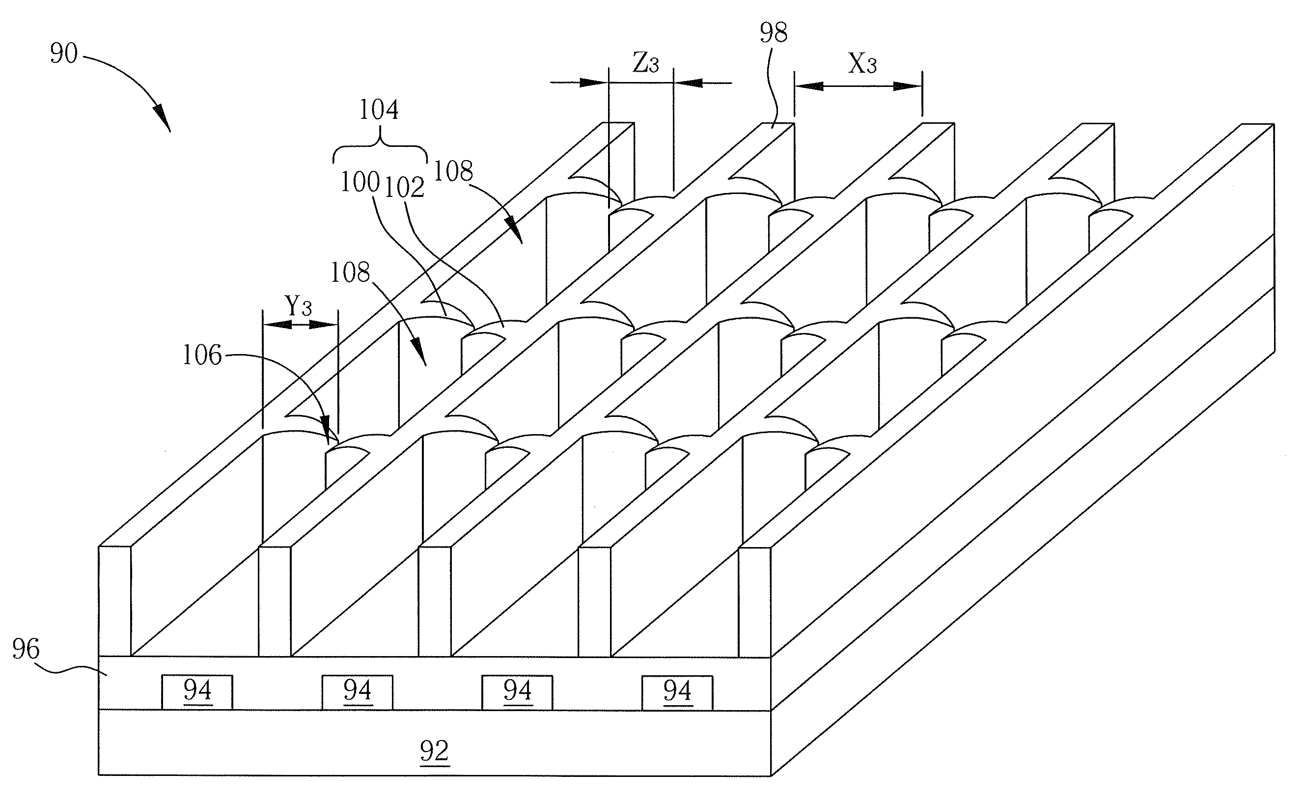
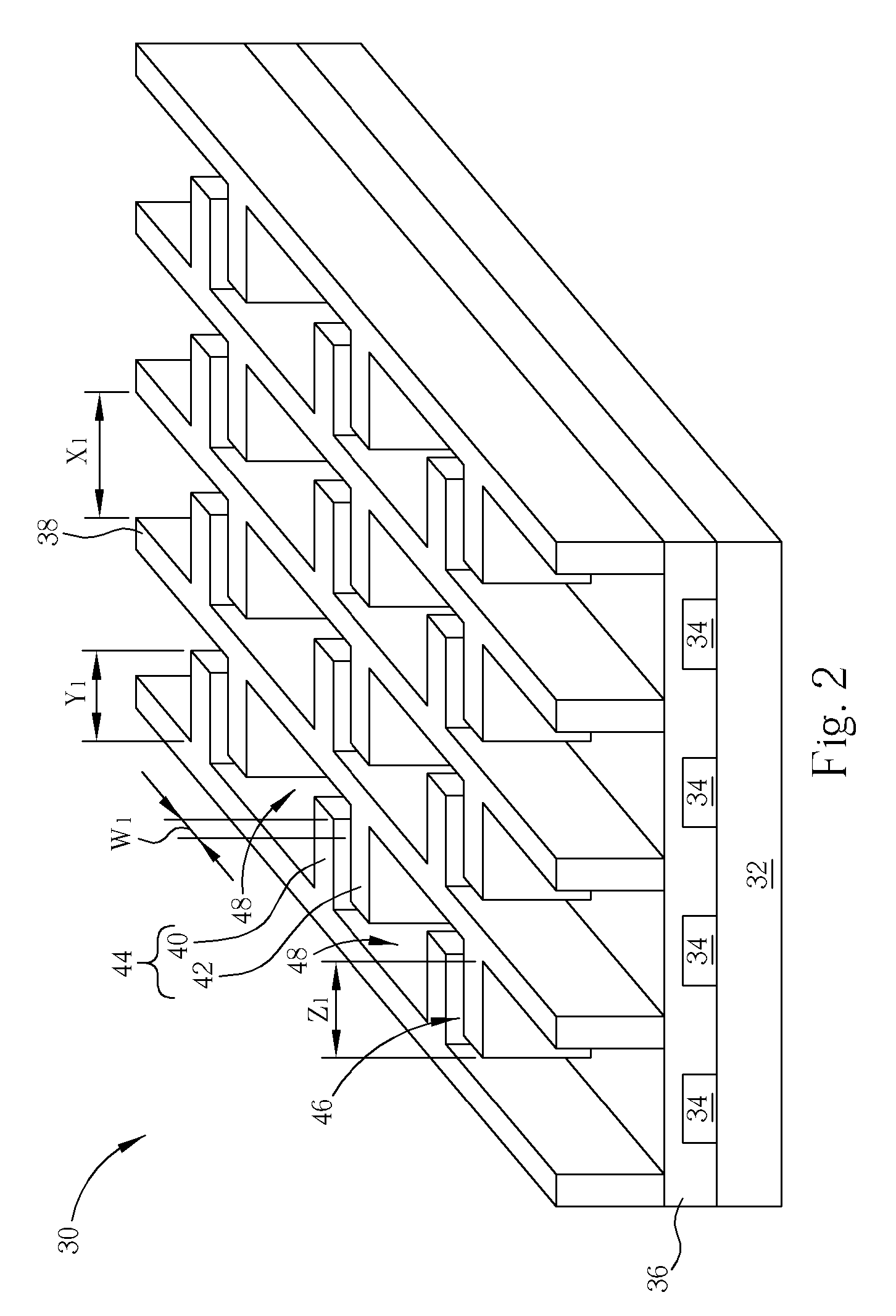
[0022]As described above, the barrier rib structure 30 of the present invention includes the plurality of vertical barrier ribs 38 arranged in parallel, such that a first distance X1 is generated between two vertical barrier ribs 38 adjacent to each other. Additionally, the plurality of first horizontal barrier ribs 40 arranged in parallel is connected to one side of the vertical barrier ribs 38, such as the right side, the plurality of second horizontal barrier ribs 42 is connected to the other side of the vertical barrier ribs 38, such as the left side, and each first horizontal barrier rib 40 is disposed alternately with corresponding second horizontal barrier ribs 42 to form a plurality of double blockade structures 44. The first horizontal barrier ribs 40 include a first length Y1 and the second horizontal barrier ribs 42 include a second length Z1, and the sum of the first length Y1 and the second length Z1 is greater than the first distance X1 for preventing the global breakd...

third embodiment

[0031]Essentially, the method fabricating the barrier rib structure 60 and barrier rib structure 90 from the second and third embodiment of the present invention includes the following steps. First, a substrate is provided, and a paste is coated over the surface of the substrate to form a barrier rib pattern after the paste is dried, in which the barrier rib pattern includes a plurality of vertical barrier ribs arranged in parallel, a plurality of parallel arranged first horizontal barrier ribs connected to one side of the vertical barrier ribs and a plurality of parallel arranged second horizontal barrier ribs connected to the other side of the vertical barrier ribs, such that the first horizontal barrier ribs and the corresponding second horizontal barrier ribs are disposed alternately to form a plurality of double blockade structures. Next, a firing process is performed to fire the barrier rib patterns, in which the first horizontal barrier ribs and the second horizontal barrier ...


PUM


Abstract

A barrier rib structure of plasma display panel is disclosed. The barrier rib structure includes a plurality of vertical barrier ribs arranged in parallel, a plurality of first horizontal barrier ribs connected to one side of the vertical barrier ribs, and a plurality of second horizontal barrier ribs connected to the other side of the vertical barrier ribs, in which the first horizontal barrier ribs are disposed alternately with corresponding second horizontal barrier ribs for forming a plurality of double blockade structures. Additionally, a gas passage and a plurality of electrical discharge spaces are formed between the double blockade structures.

Description

BACKGROUND OF THE INVENTION[0001]1. Field of the Invention[0002]The present invention relates to the barrier rib structure of a plasma display panel and a manufacturing method thereof, and more particularly, to a barrier rib structure and manufacturing method capable of improving illumination efficiency and gas exhaust of a plasma display panel.[0003]2. Description of the Prior Art[0004]Plasma display panels (PDPs) have been gradually applied to large sized displaying apparatuses. The light source comes from plasma, which is initiated by electrodes, to produce ultraviolet rays. When the ultraviolet rays excite different fluorescent materials, the fluorescent materials will emit visible light having different wavelengths. In general, the PDPs have advantages of thin and lightweight design, large display size, and wide viewing angle over the cathode ray tubes (CRTs) that have been mainly employed as display devices. Therefore, PDPs are currently very popular.[0005]In general, the barr...

Claims


Application Information

Patent Timeline
Patent Type & Authority Patents(United States)
IPC IPC(8): H01K1/18
CPCH01J9/242H01J11/12H01J11/36H01J11/54H01J2211/365
Inventor LIN, CHUN-HSUHSU, CHAO-HUNG
Owner CHUNGHWA PICTURE TUBES LTD
Why Eureka
Try Eureka