
Member switching apparatus, lens switching apparatus, laser repair apparatus, and laser inspection apparatus

a lens and switching technology, applied in semiconductor/solid-state device testing/measurement, manufacturing tools, instruments, etc., can solve the problems of deteriorating positioning accuracy, difficult to position the lens with high precision, so as to achieve high precision and quickly cancel the effect of positional shifting

Inactive Publication Date: 2008-11-18
LASERFRONT TECH
View PDF16 Cites 0 Cited by
  • Summary
  • Abstract
  • Description
  • Claims
  • Application Information

AI Technical Summary

Benefits of technology

[0008]An object of the present invention is to provide a member switching apparatus, a lens switching apparatus, as well as a laser repair apparatus and a laser inspection apparatus which can position a member, such as a lens, with high precision and when positional shifting occurs, quickly cancel the positional shifting using a simple mechanism.
[0010]In this invention, one member to be positioned at the fixed position mentioned above can be selected from the plurality of members by moving the holder using the linear motor table. Since the linear motor table is used at this time, it is difficult for positional shifting to occur in a direction other than the movement direction of the holder, thereby making it possible to position the member with high precision. Even if positional shifting occurs in the movement direction of the holder, the position of the member can be quickly adjusted and the positional shifting cancelled through the use of the linear motor table.
[0012]In the present invention, because the holder is moved by the linear motor table, it is difficult for positional shifting to occur in a direction other than the movement direction of the holder, thereby making it possible to position the lens with high precision. Even if positional shifting occurs in the movement direction of the holder, the position of the lens can be quickly adjusted and the positional shifting cancelled by driving the linear motor table.
[0016]According to the present invention, because the member to be used is switched by the linear motor table moving the holder, the member can be positioned with high precision. In addition, even if positional shifting occurs in the movement direction of the holder, the positional shifting can be quickly cancelled by driving the linear motor table. Consequently, a simplified mechanism can be provided to cancel positional shifting.

Problems solved by technology

This conventional technology has the following types of problems however.
In a rotating type lens switching device, positional shifting of the lens occurs making it difficult to position the lens with high precision due to the fact that the circular plate whereon is mounted a plurality of lenses decenters.
In addition, because a gear wheel is provided in the mechanism that rotates the circular plate and switches the lens, backlash occurs, making it more difficult to position the lens with high precision.
The gear wheel also wears down with the passage of time, deteriorating the positioning accuracy.
Because the positional shifting of the objective lens occurs in a circular path, the mechanism to cancel this positional shifting is a very complex device.
Consequently, the cost of the lens switching apparatus increases along with a considerable amount of time being required to adjust the lens position.

Method used


Image

  • Member switching apparatus, lens switching apparatus, laser repair apparatus, and laser inspection apparatus
  • Member switching apparatus, lens switching apparatus, laser repair apparatus, and laser inspection apparatus
  • Member switching apparatus, lens switching apparatus, laser repair apparatus, and laser inspection apparatus

Examples


Embodiment Construction

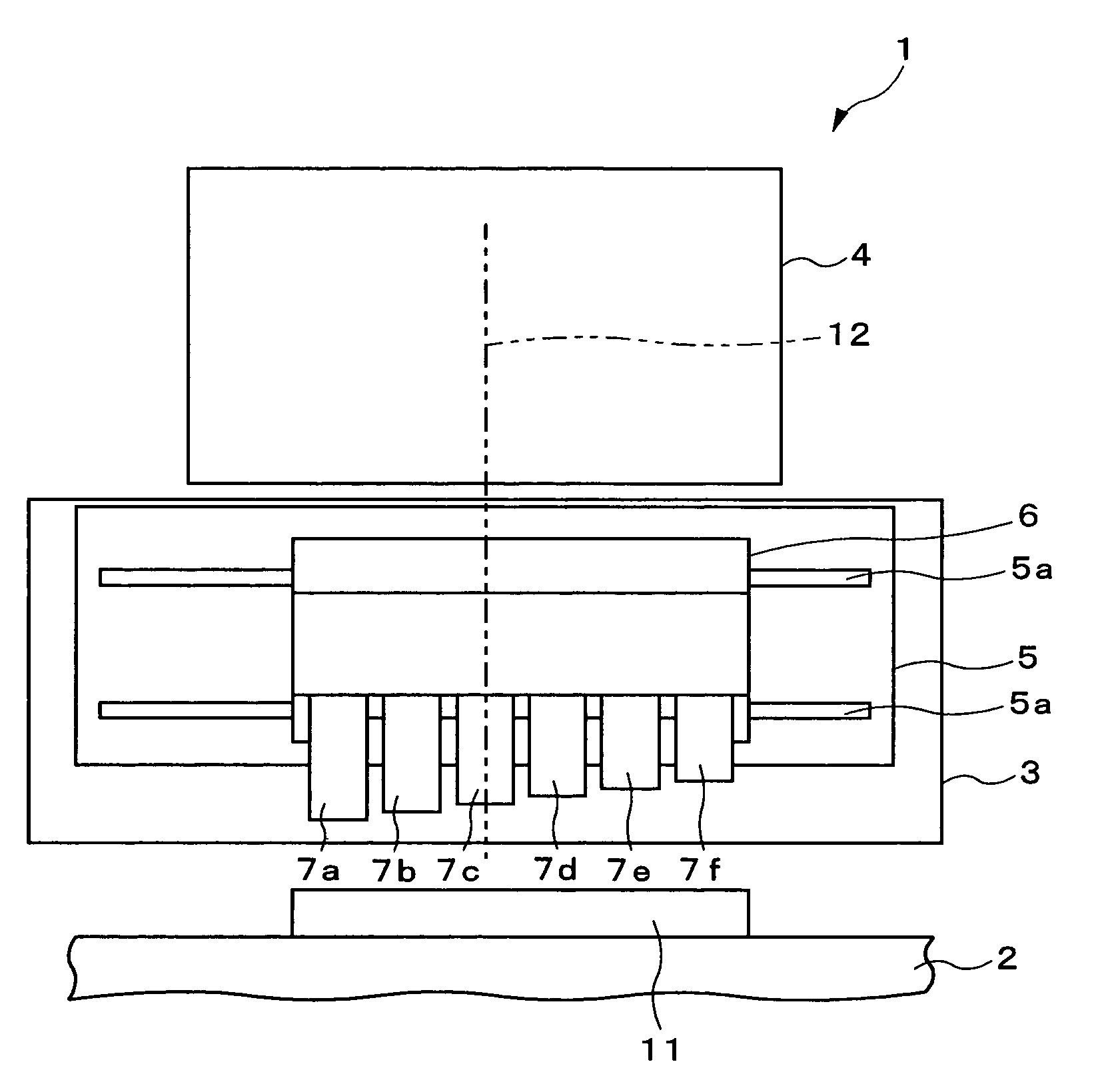
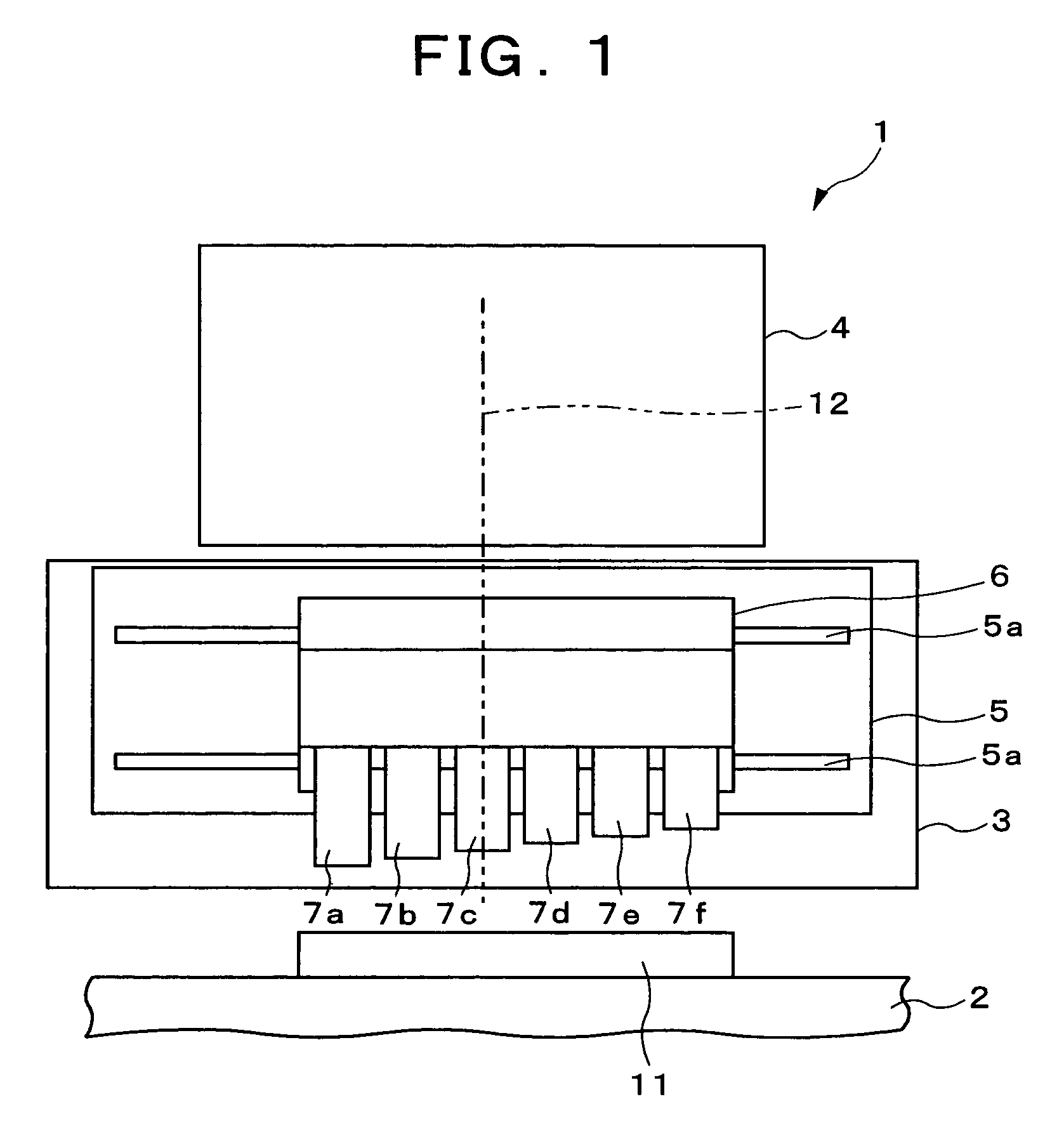
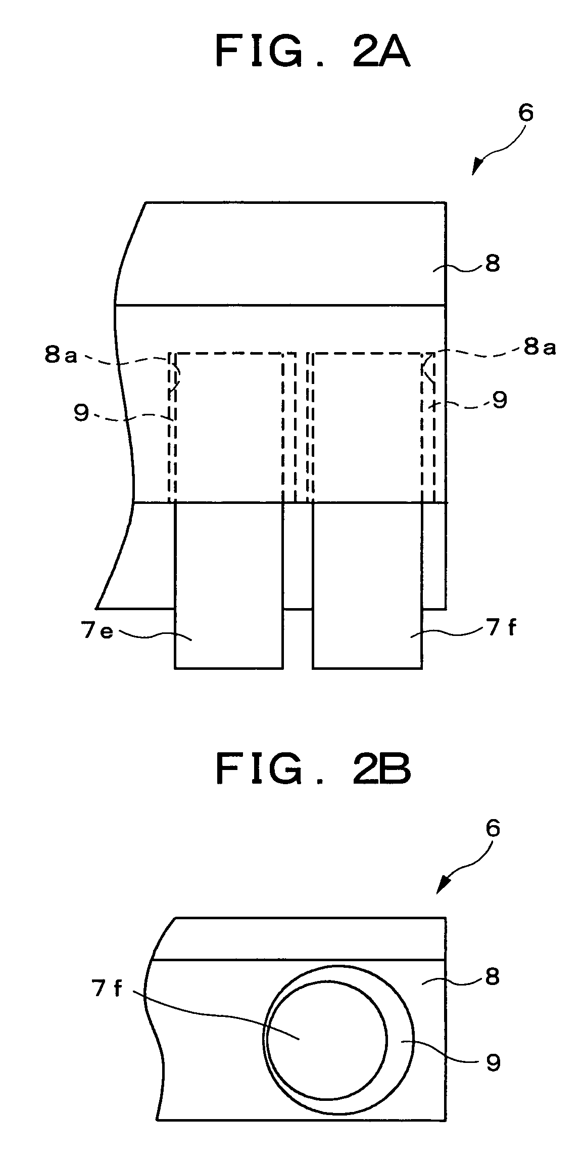
[0019]In the following, an embodiment of the present invention will be described in detail with reference to the accompanying drawings. FIG. 1 is a side view showing the laser repair apparatus according to the embodiment of the present invention. FIG. 2A is a side view showing the lens holder in the embodiment and FIG. 2B shows the lower side of the lens holder. As shown in FIG. 1, a table 2 is provided in the laser repair apparatus according to this embodiment and a work piece 11 (object to be repaired) is placed on this table 2. The work piece 11 is a semiconductor device or a liquid crystal display device being manufactured.

[0020]A lens switching apparatus 3 is provided on the table 2 and a laser oscillator 4 is provided on the lens switching apparatus 3. A laser source (not shown in figure) that emits laser light and an optical device (not shown in figure) that shapes oscillated laser light into a repaired shape are provided to the laser oscillator 4. The laser oscillator 4 dire...


PUM

PropertyMeasurementUnit
optical axisaaaaaaaaaa
opticalaaaaaaaaaa
optical axesaaaaaaaaaa

Abstract

A linear motor table is provided in a lens switching apparatus of a laser repair apparatus. The linear motor table is fixed with respect to a table and a laser oscillator and moves a lens holder in a horizontal direction. Six objective lenses with magnifications different from each other are provided and are held in a lens holder in a row such that the optical axes thereof are parallel to each other. The objective lens placed in the light path of laser light is switched by the linear motor table moving the lens holder. Because of this, a member, such as a lens, can be positioned with high accuracy and if positional shifting occurs, it can be quickly cancelled using a simple mechanism.

Description

BACKGROUND OF THE INVENTION[0001]1. Field of the Invention[0002]The present invention relates to a member processing apparatus that switches a plurality of members and selects one member, a lens switching apparatus that switches lenses positioned within an optical path, as well as a laser repair apparatus and a laser inspection apparatus equipped with this lens switching apparatus.[0003]2. Description of the Related Art[0004]Conventionally, in manufacturing processes of semiconductor devices and liquid crystal display devices, laser repair apparatuses, which perform repairs on these devices, as well as laser inspection apparatuses, which perform inspections on these devices, have been used. For example, repairs to parts needing repair are carried out by a laser oscillator in a laser repair apparatus emitting a laser light and this laser light irradiating the parts to be repaired of semiconductor devices or liquid crystal display devices.[0005]In this type of repair operation the mag...

Claims


Application Information

Patent Timeline
Patent Type & Authority Patents(United States)
IPC IPC(8): G02B15/14
CPCB23K26/0639B23K26/0648B23K26/0665G02B7/14B23K26/064H01L21/02H01L22/00
Inventor NOZAKI, MASAKAZU
Owner LASERFRONT TECH
Learn More