Laser and Photogrammetry merged process

a technology of laser tracking and photogrammetry, applied in the field of laser and photogrammetry merged process, can solve the problems of difficult measuring large surfaces, inconvenient use, and inability to accurately measure large surfaces

Active Publication Date: 2008-11-18
THE BOEING CO
View PDF15 Cites 67 Cited by
  • Summary
  • Abstract
  • Description
  • Claims
  • Application Information

AI Technical Summary

Problems solved by technology

However, Photogrammetry processes may lack precision and / or suffer from other problems.
However, laser tracking processes may take substantial time, may have difficulty measuring large surfaces, and / or may have other problems.

Method used


Image

  • Laser and Photogrammetry merged process
  • Laser and Photogrammetry merged process
  • Laser and Photogrammetry merged process

Examples


Embodiment Construction

[0013]The following detailed description is of the best currently contemplated modes of carrying out the invention. The description is not to be taken in a limiting sense, but is made merely for the purpose of illustrating the general principles of the invention, since the scope of the invention is best defined by the appended claims.

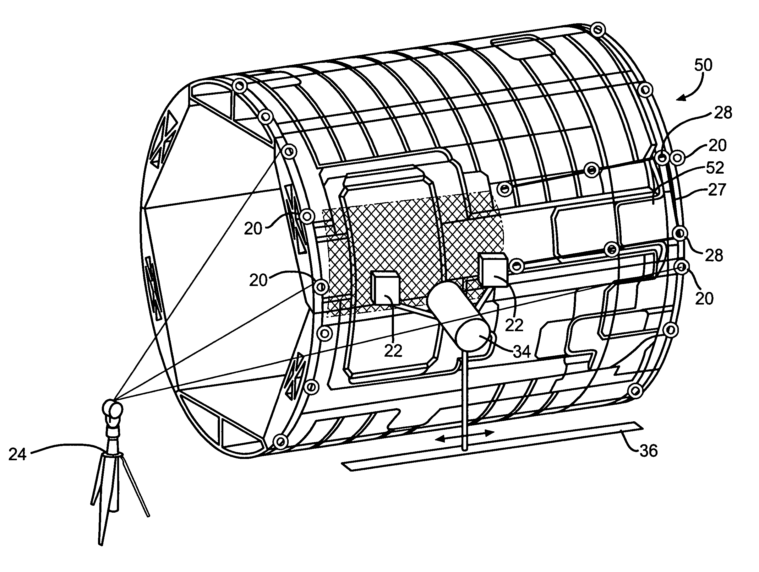
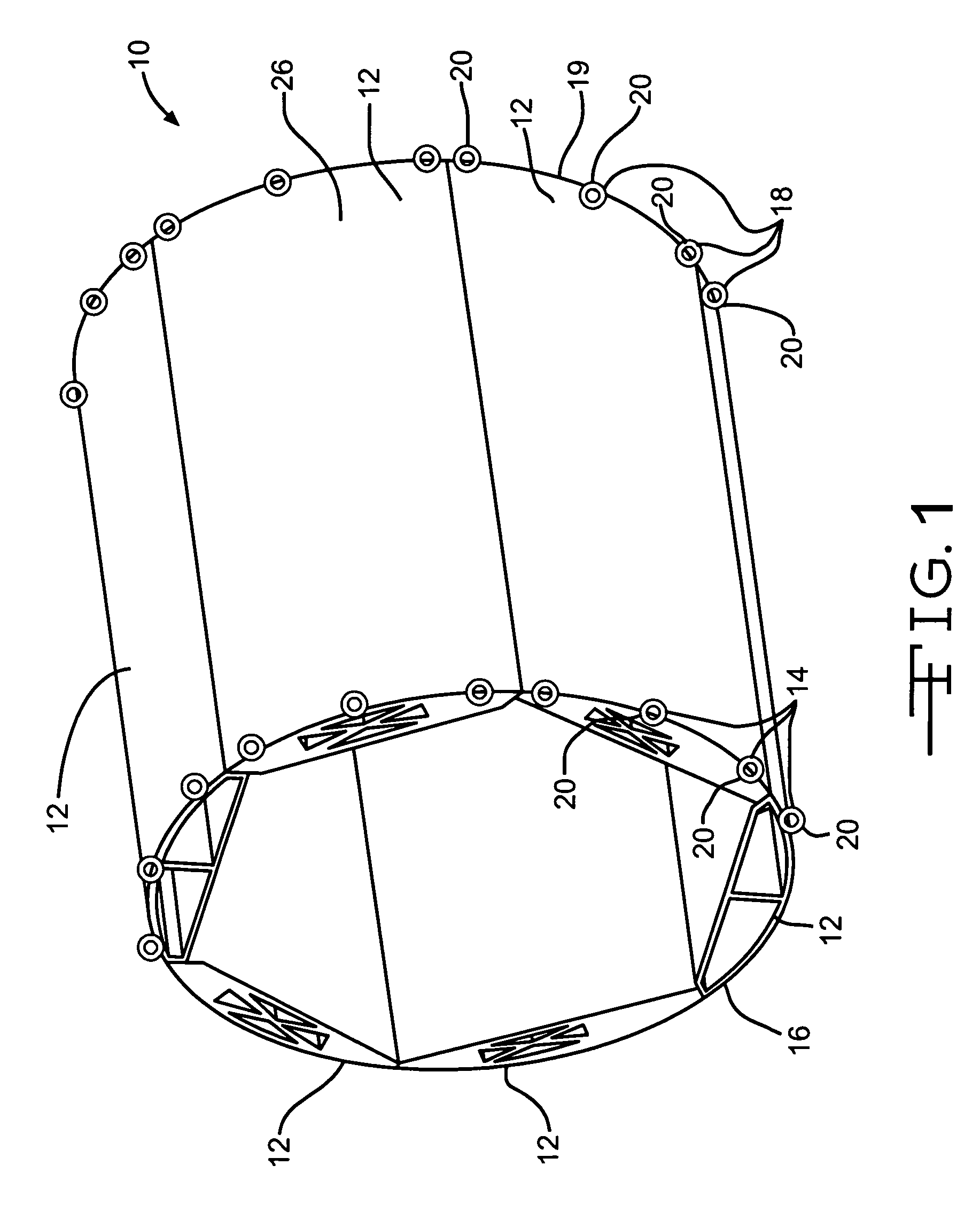
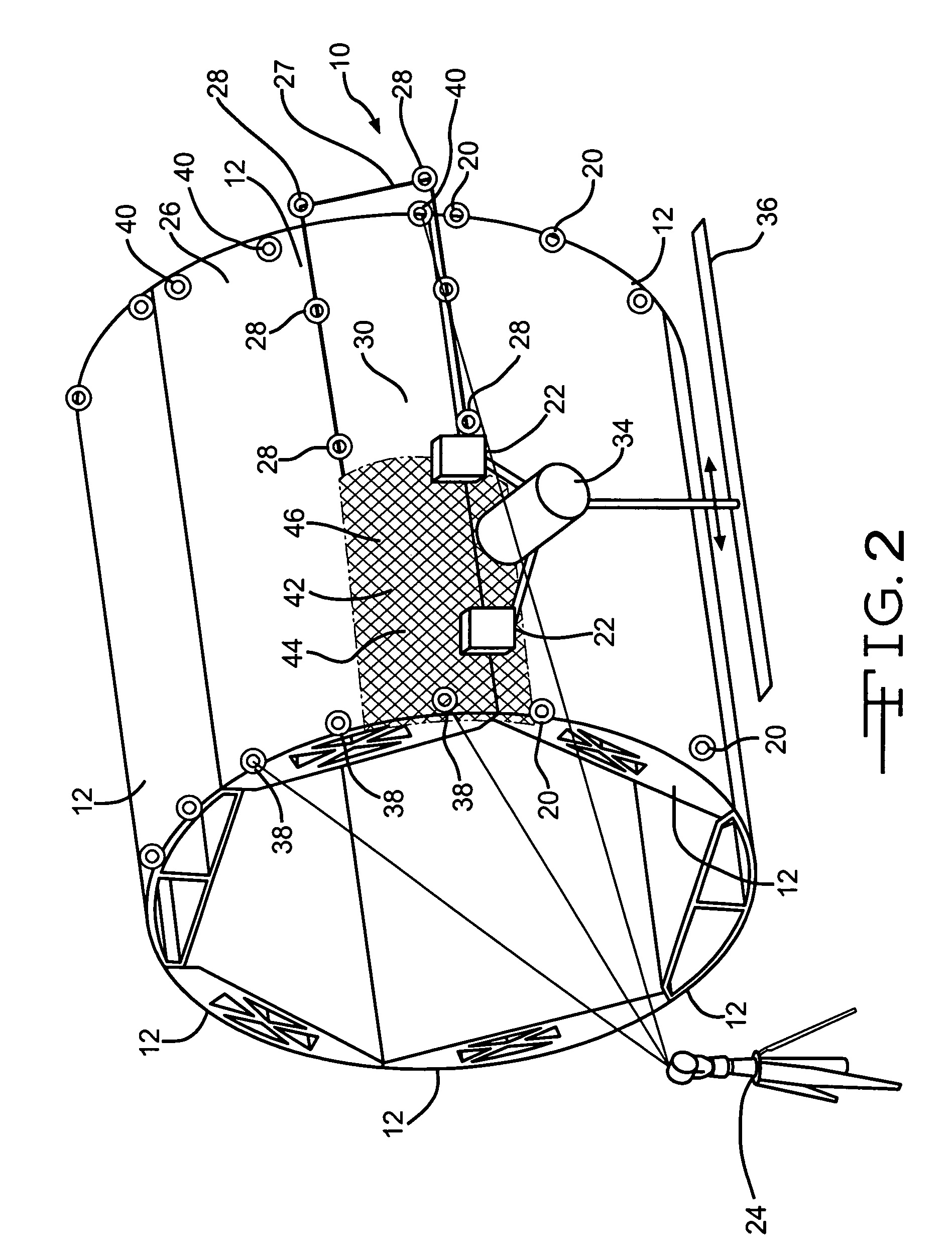
[0014]FIGS. 1 through 6 depict a step by step process under one embodiment of the invention for measuring an outer surface of a mandrel assembly and for measuring an outer surface of a barrel of an airplane. In other embodiments, the process may be varied to measure one or more differing types of surfaces on any type of part. The surface measuring process may be utilized to measure surfaces in both airplane and non-airplane applications.

[0015]FIG. 1 depicts a mandrel assembly 10, which may be made up of six steel mandrel sections 12 attached together to form a generally cylindrical shape. The mandrel sections 12 may be bolted together. In other embodime...


PUM


Abstract

The invention relates to processes for measuring one or more surfaces of a part utilizing both Photogrammetry and laser tracking devices. The measured part may comprise the barrel of an airplane. In other embodiments, varying types of surfaces may be measured in both airplane and non-airplane applications. In one embodiment, such a process may comprise measuring at least one surface of a part utilizing Photogrammetry, and simultaneously measuring the at least one surface utilizing laser tracking.

Description

BACKGROUND OF THE INVENTION[0001]Varying processes are utilized to measure one or more surfaces of a part. For instance, surfaces of a part are sometimes measured utilizing Photogrammetry. The Photogrammetry process may allow large surfaces to be measured in a timely manner. However, Photogrammetry processes may lack precision and / or suffer from other problems. Laser tracking processes are also sometimes used to measure surfaces of a part. The laser tracking process may allow precision surface measurements. However, laser tracking processes may take substantial time, may have difficulty measuring large surfaces, and / or may have other problems.[0002]A surface measuring process is needed which may alleviate one or more of the problems of the prior surface measuring processes.SUMMARY OF THE INVENTION[0003]In one aspect of the invention, a process for measuring at least one surface of a part comprises measuring the at least one surface of the part utilizing Photogrammetry, and simultane...

Claims


Application Information

Patent Timeline
Patent Type & Authority Patents(United States)
IPC IPC(8): G06F19/00
CPCG01B11/002G01C11/02G01C15/002
Inventor MARSH, BOBBY J.
Owner THE BOEING CO
Why Eureka
Try Eureka