Effort-saving gardening shears

a gardening shear and effort-saving technology, applied in the field of gardening shears, can solve the problems of difficulty in stably drilling the handles of the user's hand, roughness or even tears at the cut of the objective branch, and the defects of the foresaid conventional gardening shears, so as to achieve stable, smooth and durable operation.

Inactive Publication Date: 2008-11-25
NATURA INNOVATION LTD
View PDF9 Cites 24 Cited by
  • Summary
  • Abstract
  • Description
  • Claims
  • Application Information

AI Technical Summary

Benefits of technology

[0015]It is one object of the present invention to provide a pair of one-hand operating shears equipped with an effort-saving transmission assembly to achieve effortless operation of the gardening shears.
[0016]It is an other object of the present invention to provide a pair of effort-saving gardening shears characterized by the stable, smooth and durable operation which is accomplished by utilizing the variation of the engagement between the teeth of the toothed block and the toothed hole of the effort-saving transmission assembly to scatter the shearing force and counterforce imposed on the pivot member of the shears.
[0017]It is still another object of the present invention to provide a pair of effort-saving gardening shears which are secured against overextending or improper closing because the full open angle and close angle thereof are confined by said effort-saving transmission assembly.

Problems solved by technology

However, foresaid conventional gardening shears may have defects as described below.
Since the shearing force of the shears utterly is derived from the user's squeezing force exerted on the handles, the user may have to implement his extreme strength to operate the shears, and it can be difficult for the user to hole the handles stably while exerting such excessive squeezing force.
Thus, such difficult operation may in turn render undesirable sway, shakiness or deviation of the shears during shearing and as a result, roughness or even tears may occur at the cut of objective branch.
Further, when the excessive shearing force is imposed on the branches or stems under said excessive squeezing force, an excessive counterforce may be correspondingly incurred from the sheared branch to damage the pivot member and detrimental clearance between the shear elements may successively arise to weaken the shearing force of the shears.
Eventually, the shears can undesirably become unusable soon.

Method used


Image

  • Effort-saving gardening shears
  • Effort-saving gardening shears
  • Effort-saving gardening shears

Examples


embodiment

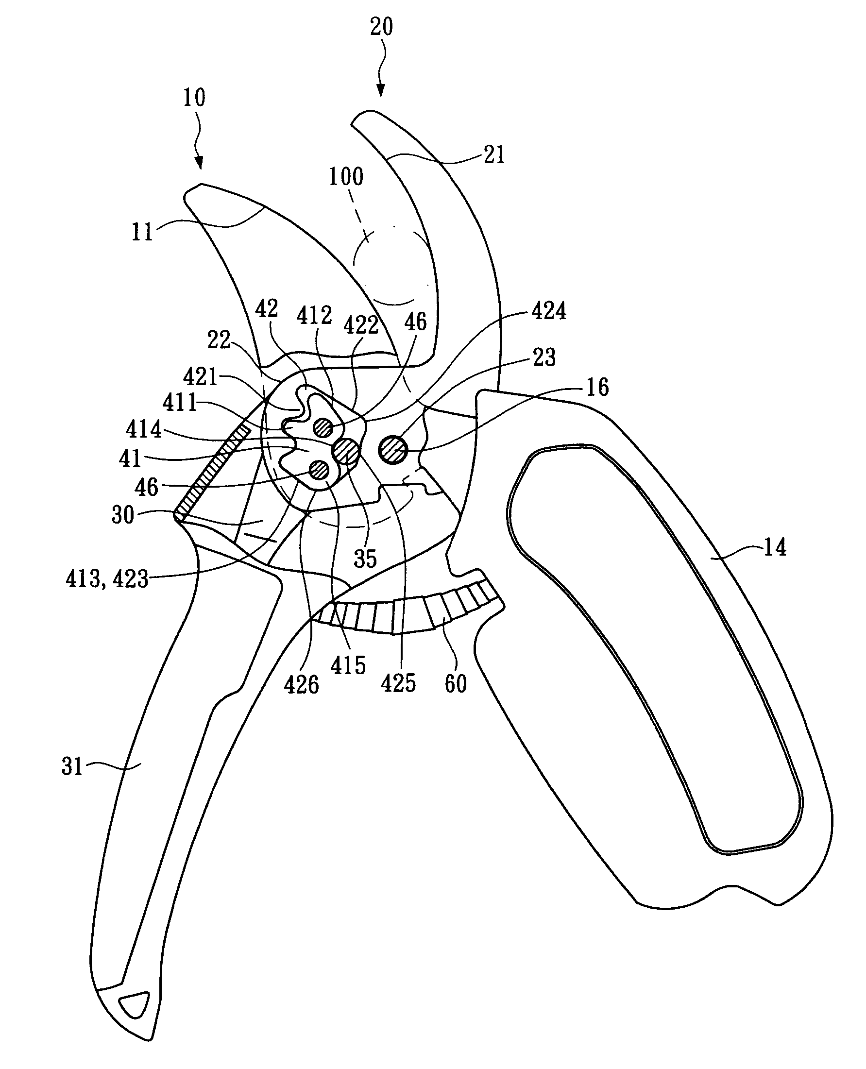
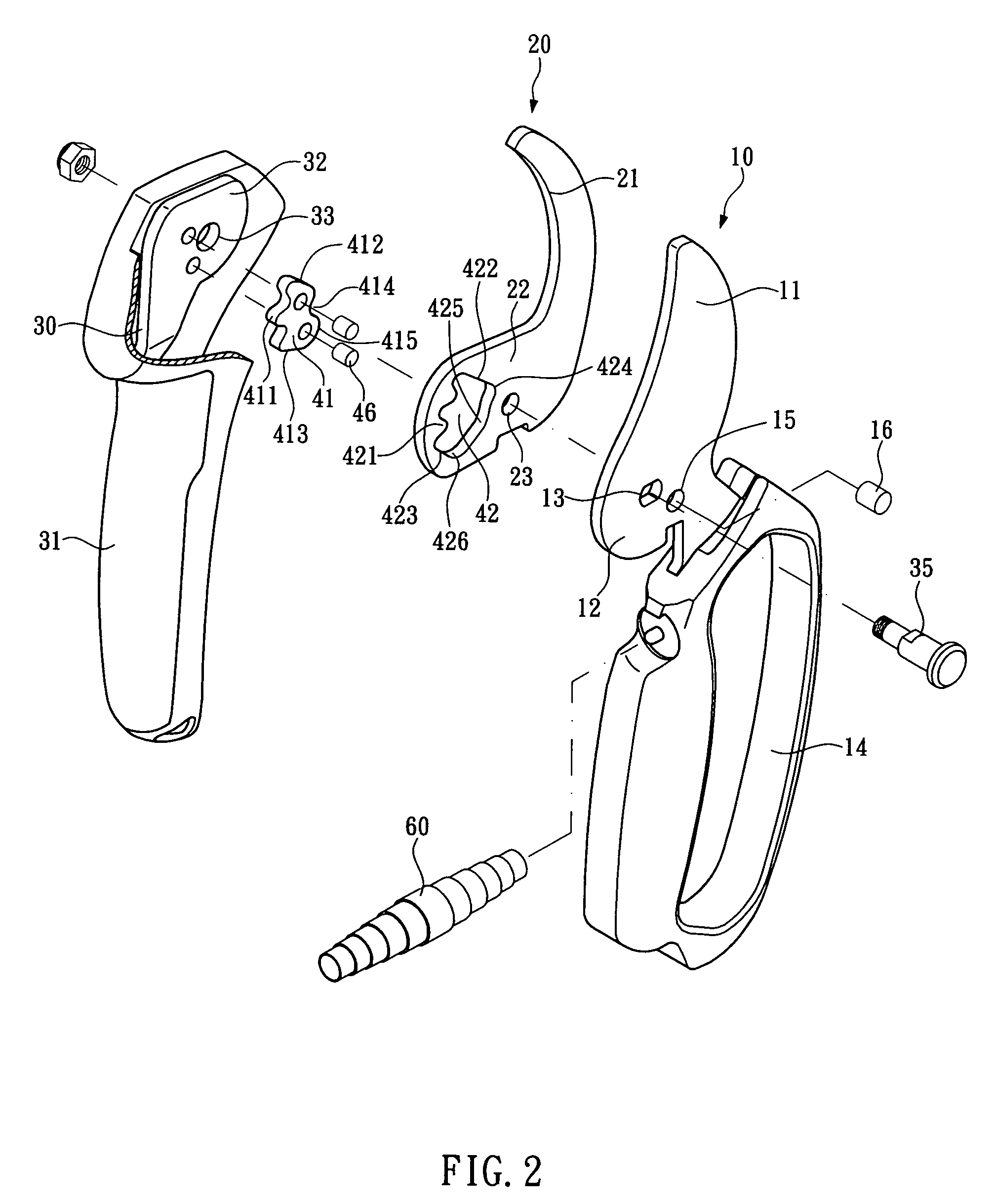
[0026]As shown in FIGS. 2 and 3, an embodiment of the disc lose d effort-saving shears primarily comprises:

[0027]a first shear element 10 having a blade portion 11 at one end, a combining portion 12 at the opposite end comprising a pivot hole 13 and a shear element combining hole 15, and a first handle 14 further attached to the first shear element 10;

[0028]a second shear element 20 having a blade portion 21 at one end, and a combining portion 22 at the opposite end comprising a shear element combining hole 23;

[0029]a handle shaft 30 axially positioned within a second handle 31 and having a combining portion 32 at one end which includes a pivot hole 33 thereon;

[0030]an effort-saving transmission assembly including a toothed block 41 fixed on one side of the combining portion 32 of the handle shaft 30, and a toothed hole 42 provided on the combining portion 22 of the second shear element 20, wherein the combining portion 22 of the second shear element 20 overlaps the combining portio...


PUM


Abstract

A pair of effort-saving shears primarily comprises: a first shear element having a combining portion with a pivot hole and a shear element combining hole thereon, and a first handle further attached to the first shear element; a second shear element having combining portion with a shear element combining hole; a handle shaft axially positioned in a second handle and having a combining portion at one end; an effort-saving transmission assembly including a toothed block fixed on one side of the combining portion of the handle shaft, and a toothed hole provided on the combining portion of the second shear element, wherein the toothed hole enclose and partially engage the toothed block by parts of the teeth thereof; and wherein the combining portion of the first shear element overlaps the combining portion of the second shear element; a pivot member, piercing through said pivot holes to be placed between the toothed hole and the toothed block; and a shear element combining pin piercing through said shear element combining pin holes.

Description

BACKGROUND OF THE INVENTION[0001]1. Technical Field[0002]The present invention relates to gardening shears and, more particularly, to a pair of shears having an effort-saving assembly for one-hand holding and operating.[0003]2. Description of Related Art[0004]A pair of conventional gardening shears, as shown in FIG. 1, typically comprises two shear elements wherein one shear element may be movable while the other may be relatively fixed and the two shear elements are crosswise combined at a pivot member. Further, one handle may be attached to each shear element at the end beyond said pivot member. When operating such conventional gardening shears, a user squeezes both handles with single hand to drive the shear elements to approach each other and a shearing force can therefore be generated for pruning branches or stems of plants.[0005]However, foresaid conventional gardening shears may have defects as described below.[0006]Since the shearing force of the shears utterly is derived fr...

Claims


Application Information

Patent Timeline
Patent Type & Authority Patents(United States)
IPC IPC(8): B26B13/28B26B13/00
CPCA01G3/02B26B13/26
Inventor SHAN, SU-HUA
Owner NATURA INNOVATION LTD
Why Eureka
Try Eureka