Tension control system and method for tensioning a strapping material around a load in a strapping machine

a technology of tension control system and strapping machine, which is applied in the field of strapping machine, can solve the problems of clutch wear and variability in the tension applied to the strap, and achieve the effect of improving the tension control system of the strap around the load

Active Publication Date: 2008-11-25
SIGNODE IND GRP
View PDF16 Cites 18 Cited by
  • Summary
  • Abstract
  • Description
  • Claims
  • Application Information

AI Technical Summary

Problems solved by technology

However this can result in wear on the clutch, and variability in the tension applied to the strap material

Method used


Image

  • Tension control system and method for tensioning a strapping material around a load in a strapping machine
  • Tension control system and method for tensioning a strapping material around a load in a strapping machine
  • Tension control system and method for tensioning a strapping material around a load in a strapping machine

Examples


Embodiment Construction

[0017]While the present invention is susceptible of embodiment in various forms, there is shown in the drawings and will hereinafter be described a presently preferred embodiment with the understanding that the present disclosure is to be considered an exemplification of the invention and is not intended to limit the invention to the specific embodiment illustrated.

[0018]It should be further understood that the title of this specification, namely, “detailed Description of the Invention”, relates to a requirement of the United States Patent Office, and does not imply, nor should be inferred to limit the subject matter disclosed herein.

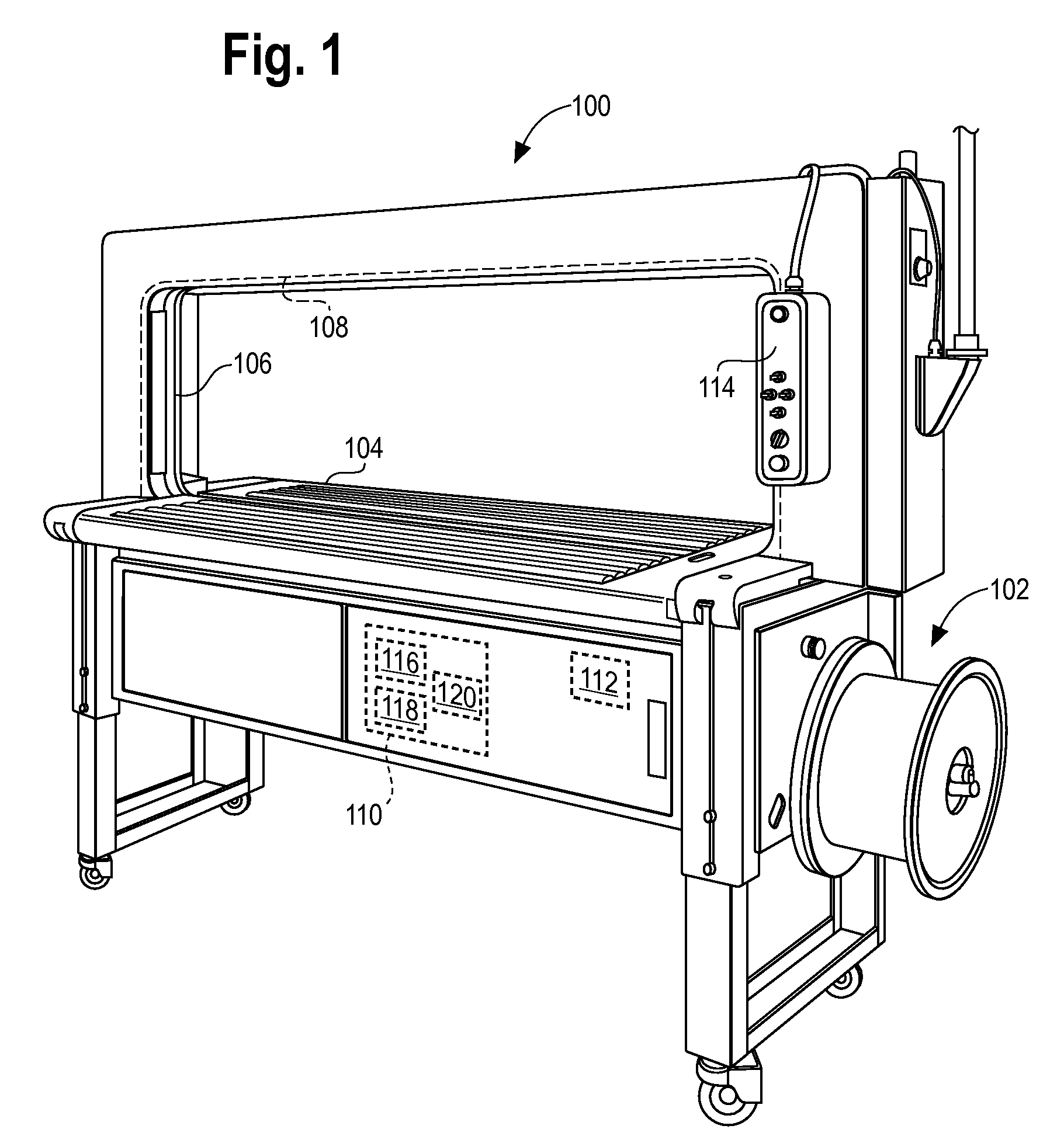
[0019]Referring to the figures, and in particular to FIG. 1, there is shown one exemplary embodiment of a strapping machine 100 that may be used with the present invention. Of course, as would be understood by one of ordinary skill in the art, the present invention may be used with various types of strapping machines having various configurations.

[0020]...


PUM


Abstract

A strapping machine is provided to feed a strap around a load, position, tension and seal the strap around the load. The strapping machine includes a surface to support the load in the strapping machine; a strap chute to carry a strap around the load and release the strap from the strap chute; a motor assembly to convey the strap around the strap chute, retract the strap material around the load, and tension the strap around the load; and an adjustable speed drive capable of receiving a first reference signal and a second reference signal, and configured to actuate the motor assembly to apply a first amount of torque to the strap when receiving the first reference signal and to apply a second amount of torque to the strap when receiving the second reference signal. The strapping machine also includes a controller configured to operate the adjustable speed drive in a first mode while conveying the strap around the strap chute and retracting the strap material around the load, and a second mode while tensioning the strap around the load. In the first mode, the adjustable speed drive actuate the motor assembly to apply the first amount of torque to the strap, and in the second mode, the adjustable speed drive actuates the motor assembly to apply the second amount of torque to the strap.

Description

BACKGROUND OF THE INVENTION[0001]The present invention is directed to a strapping machine. More particularly, the present invention is directed to an improved tension control system for tensioning a strap around a load in a strapping machine.[0002]Strapping machines are in widespread use for securing straps around loads. There are various types of strappers. One type of strapper is a stationary arrangement in which the strapper is stand-alone device that is part of an overall manufacturing of fabrication operation.[0003]In a stand-alone strapper, a strapping head and drive mechanisms (feed and take-up) are typically mounted within a frame. A chute is likewise mounted to the frame, through which the strapping material is fed.[0004]In one known configuration, a strapping head is mounted at about a work surface, and the chute is positioned above the work surface and above the strapping head. Strap material is fed to the strapping head, and is then driven by feed wheels (by a motor) to ...

Claims


Application Information

Patent Timeline
Patent Type & Authority Patents(United States)
IPC IPC(8): B65B13/22
CPCB65B13/06B65B13/10B65B13/22
Inventor MORRISON, ARLAND
Owner SIGNODE IND GRP
Why Eureka
Try Eureka