Instrument for bending spinal rods used in a spinal fixation system

a technology of spinal rods and instruments, applied in the field of spinal rod fixation systems, can solve the problems of difficult control of french benders and other known instruments for bending spinal rods, inability to easily bend, and significant force required to bend rods, etc., to achieve easy operation, small force, and easy control

Inactive Publication Date: 2008-11-25
DEPUY SPINE INC (US)
View PDF10 Cites 61 Cited by
  • Summary
  • Abstract
  • Description
  • Claims
  • Application Information

AI Technical Summary

Benefits of technology

[0006]The present invention provides an improved instrument and method for bending a spinal rod or other surgical implant to conform to a desired form, for example, the curvature of the spinal column in one or more anatomic planes. The instrument for bending a spinal rod includes a lever pivotally connected to a handle through a movable linkage system. The movable linkage system includes one or more bearing surfaces for applying a force to a first portion of the rod while a rod seat connected to the handle holds an adjacent second portion of the rod in a fixed position, thereby causing the rod to bend between the first and second portion. The instrument can be easily operated using a single hand, is easy to control and requires a relatively small amount of force to bend a rod. The instrument can include an automatic advancement means, such as a ratchet, pawl or frictional latch, for advancing the rod after bending to bend another portion of the rod by a selected amount. The instrument can also be used for bending rods having a non-circular cross-section in multiple planes.

Problems solved by technology

Because spinal rods are formed of materials that are not easily bendable, such as titanium, a significant amount of force is required to bend the rods.
French benders and other known instruments for bending spinal rods are also difficult to control for producing accurate and reproducible curves.
In addition, the “French bender” is generally only configured to receive rods having a circular cross-section and cannot easily bend rods having a non-circular cross-section.

Method used


Image

  • Instrument for bending spinal rods used in a spinal fixation system
  • Instrument for bending spinal rods used in a spinal fixation system
  • Instrument for bending spinal rods used in a spinal fixation system

Examples


Embodiment Construction

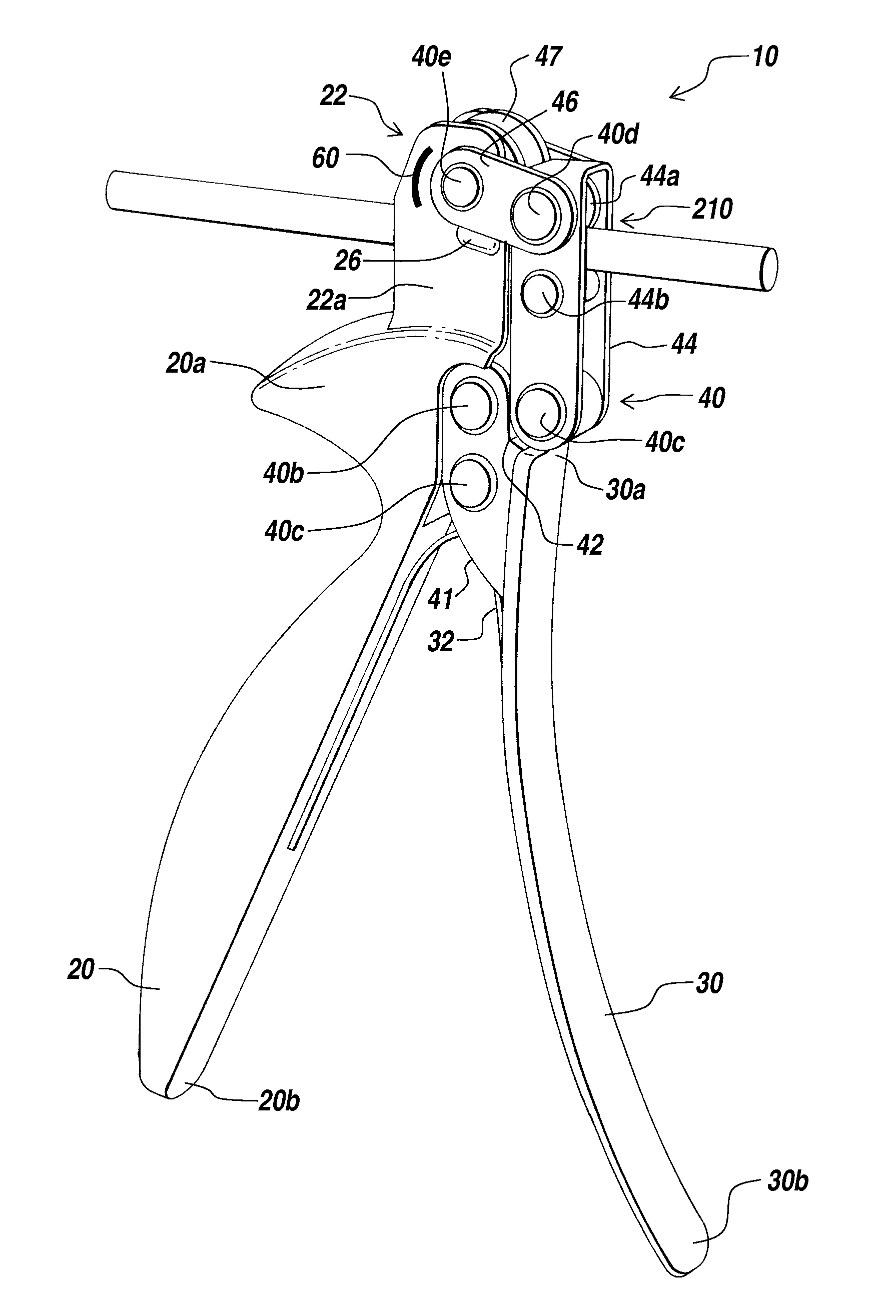
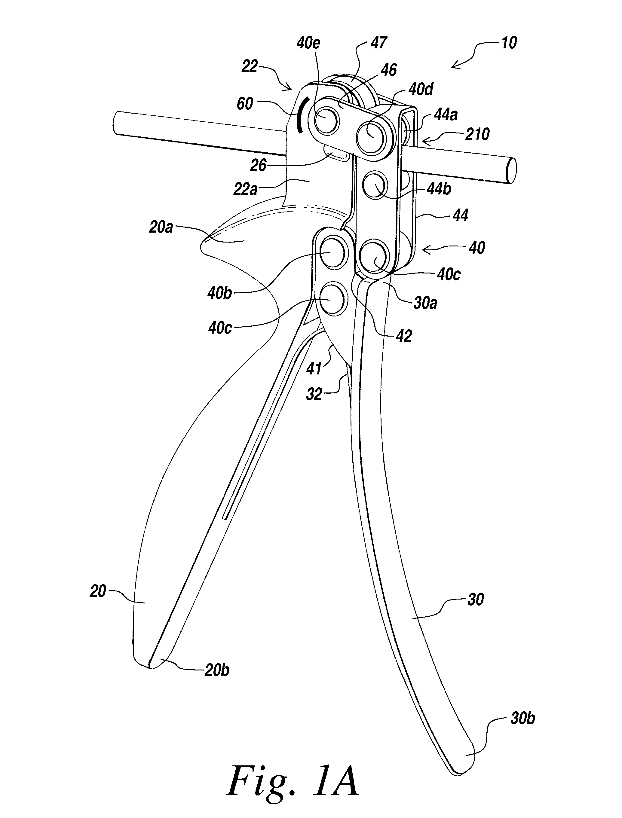
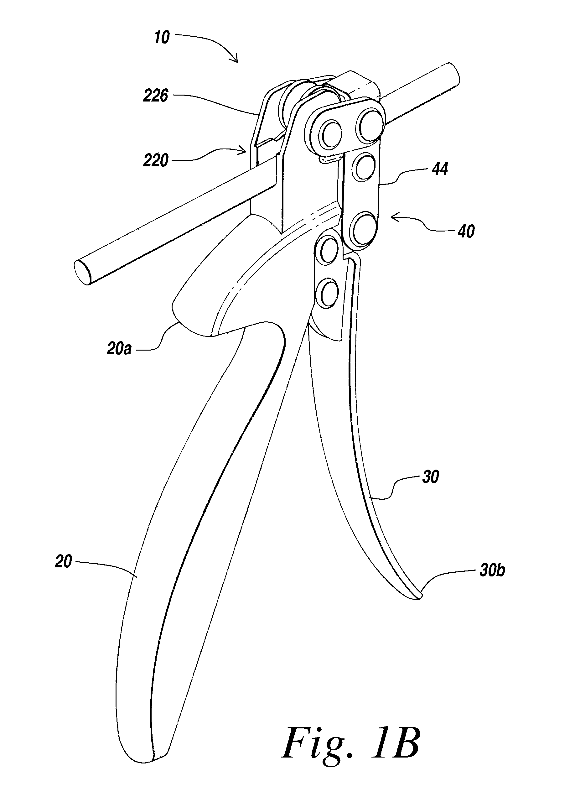
[0020]The present invention provides an improved instrument for bending a component of a spinal fixation system, such as a surgically implantable spinal rod. The illustrative instrument can be used to bend, straighten, adjust or otherwise change the bend of a spinal rod using less manual force than prior rod bending systems. The present invention will be described below relative to an illustrative embodiment. Those skilled in the art will appreciate that the present invention may be implemented in a number of different applications and embodiments and is not specifically limited in its application to the particular embodiments depicted herein.

[0021]The terms “upper”, “top”, “lower”, “bottom”, “forward”, “front”, “rearward” and “back” are relative terms used to describe the position and orientation of different components of the instrument relative to each other, and are not intended to limit the invention in any way.

[0022]Referring to FIGS. 1A-1E, a rod-bending instrument 10 of an i...


PUM

PropertyMeasurementUnit
forceaaaaaaaaaa
movementaaaaaaaaaa
anatomical structureaaaaaaaaaa

Abstract

An instrument and method for bending a surgical implant, such as a spinal rod, includes a lever pivotally connected to a handle through a movable linkage system. The movable linkage system includes one or more bearing surfaces for applying a force to a first portion of the surgical implant while a rod seat connected to the handle holds an adjacent second portion of the surgical implant in a fixed position, thereby causing the surgical implant to bend between the first and second portion. The instrument can be easily operated using a single hand, is easy to control and requires a relatively small amount of force to bend a surgical implant. The instrument can include an automatic advancement means for advancing the surgical implant after bending to bend another portion of the surgical implant by a selected amount. The instrument can also be used for bending spinal rods having a non-circular cross-section in multiple planes.

Description

RELATED APPLICATIONS[0001]The present invention relates to U.S. patent application Ser. No. 11 / 035,282 entitled “Instrument for Bending Spinal Rods Used in a Spinal Fixation System”, filed on even date herewith.FIELD OF THE INVENTION[0002]The present invention relates to spinal fixation systems used in orthopedic surgery to align, adjust and / or fix portions of the spinal column. More particularly, the present invention relates to an instrument for bending a spinal rod used in a spinal fixation system to conform to a desired curvature of the spinal column in one or more anatomic planes.BACKGROUND OF THE INVENTION[0003]Spinal fixation systems may be used in surgery to align, adjust and / or fix portions of the spinal column, i.e., vertebrae, in a desired spatial relationship relative to each other. Many spinal fixation systems employ a spinal rod for supporting the spine and for properly positioning components of the spine for various treatment purposes. The spinal rods, which are gener...

Claims


Application Information

Patent Timeline
Patent Type & Authority Patents(United States)
IPC IPC(8): B21D7/02B21D7/024
CPCA61B17/8863B21D7/063B21D39/048
Inventor GARNER, RONALDRUNCO, THOMAS J.
Owner DEPUY SPINE INC (US)
Why Eureka
Try Eureka