Well jet device for logging horizontal wells and the operating method thereof

a technology of horizontal wells and well jets, which is applied in the field of pumping engineering, can solve the problems of reducing the possibility of drilling, increasing the time required for full value studies, and not being able to fully utilize its capabilities, so as to improve the reliability of drilling operations, simplify the design of drilling devices, and control the depression value

Inactive Publication Date: 2008-11-25
KHOMYNETS ZINOVIY DMITRIEVICH
View PDF10 Cites 2 Cited by
  • Summary
  • Abstract
  • Description
  • Claims
  • Application Information

AI Technical Summary

Benefits of technology

[0014]An analysis of the well jet device operation shows that the operational reliability may be improved both by optimizing the sequence of actions carried out during testing and completing wells, first of all with open or curvilinear boreholes and by simplifying the design of the device for which a packer is excluded from the design and the logging device is arranged on the tubing string without using the logging cable.
[0015]It has been found that the above sequence of actions enables most efficiently use the equipment, which is arranged on the tubing string, during works on studying and testing production formations in rocks by forming conditions for obtaining full and reliable information on the condition of the production formations. By creating a series of different-value depressions the jet pump forms in a well the given values of pressure differential, and the well is studied and tested with the use of the logging device. Simultaneously, it is possible to control depression values by controlling the pumping rate of the operating fluid. By carrying out formation testing it is possible to adjust the pumping-out mode by changing the pressure of the operating fluid fed into the nozzle of the jet pump. The arrangement of the logging device on the tubing string with the possibility of axial movement and without using a packer (the sealing unit put on the tubing string is used instead of a packer) enables to carry out better work on testing a well and preparing it for operation and, as a consequence, make the process of testing and completing a well quicker and simpler. Furthermore, the arrangement of the logging device on the tubing string gives the possibility, due to the tubing string elastic properties, of arranging the logging device in the area of production formations in horizontal sections of wells, which enables to obtain reliable information on the condition of production formations, a formation fluid inflow and its properties quicker. As a result, this operation regime enables to carry out quality studies and tests of wells after drilling as well as preparation of wells for operation on the basis of a comprehensive study and its testing in different regimes.
[0016]Thus, the above totality of the interdependent sequence of actions and the above-stated design features of the well jet device ensures the fulfillment of the task stated for the invention, namely, to intensify works on studying and testing wells, primarily horizontal wells and those of great curvature, as well as to improve the operational reliability of the well jet device.

Problems solved by technology

They, however, do not enable to carry out works on treating the near-borehole area in a formation, which lowers their possibilities.
But, the cited device does not enable to utilize its capabilities in full, since it enables to study producing rocks only in boreholes close to vertical, which narrows the field of using that operating method and that well jet device for realizing it.
Furthermore, a rearrangement of the jet pump is a rather labor-consuming operation requiring release of the packer for its subsequent installation in a new place, which increases the time necessary for carrying out a full-value study.

Method used


Image

  • Well jet device for logging horizontal wells and the operating method thereof
  • Well jet device for logging horizontal wells and the operating method thereof
  • Well jet device for logging horizontal wells and the operating method thereof

Examples


Embodiment Construction

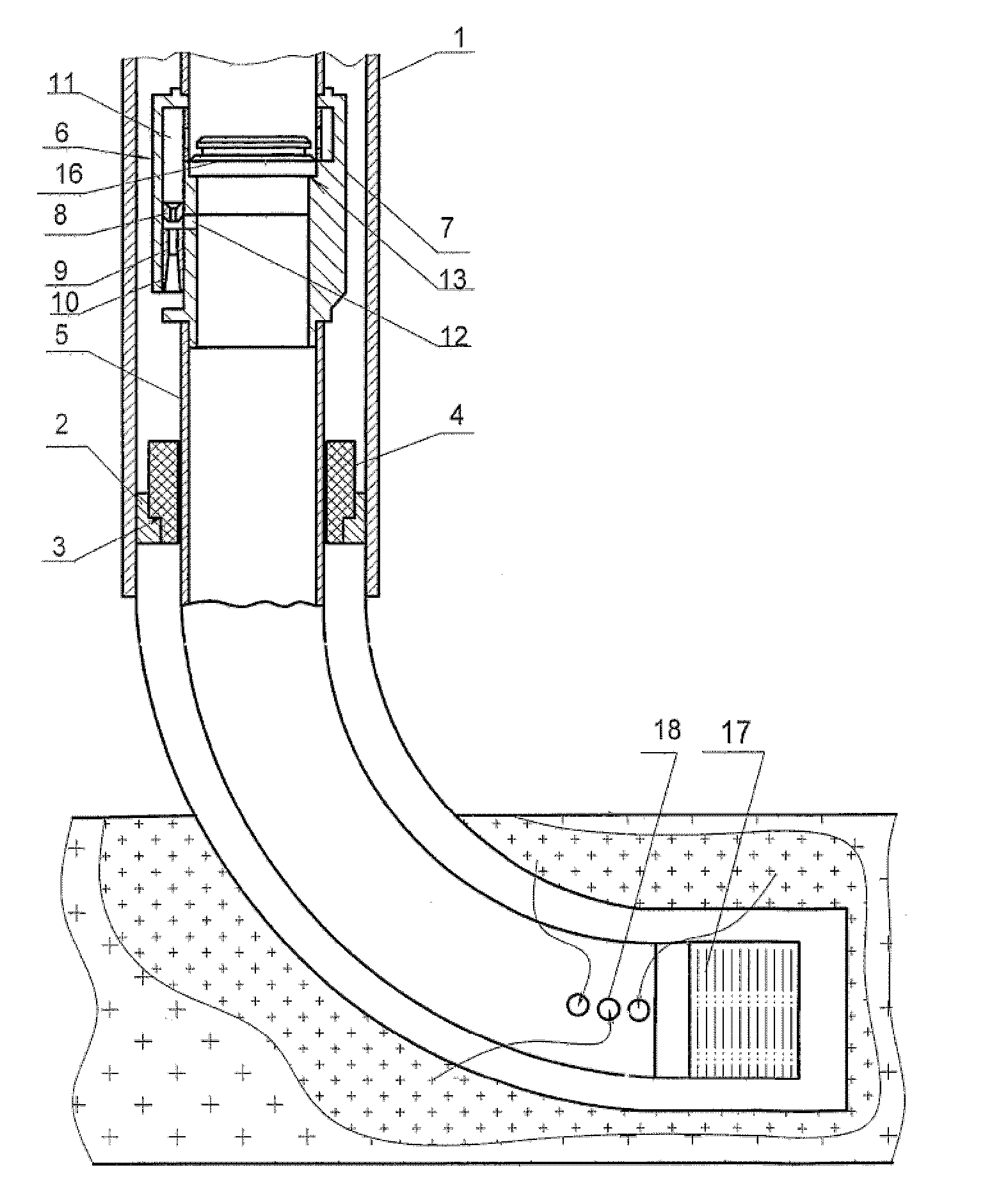
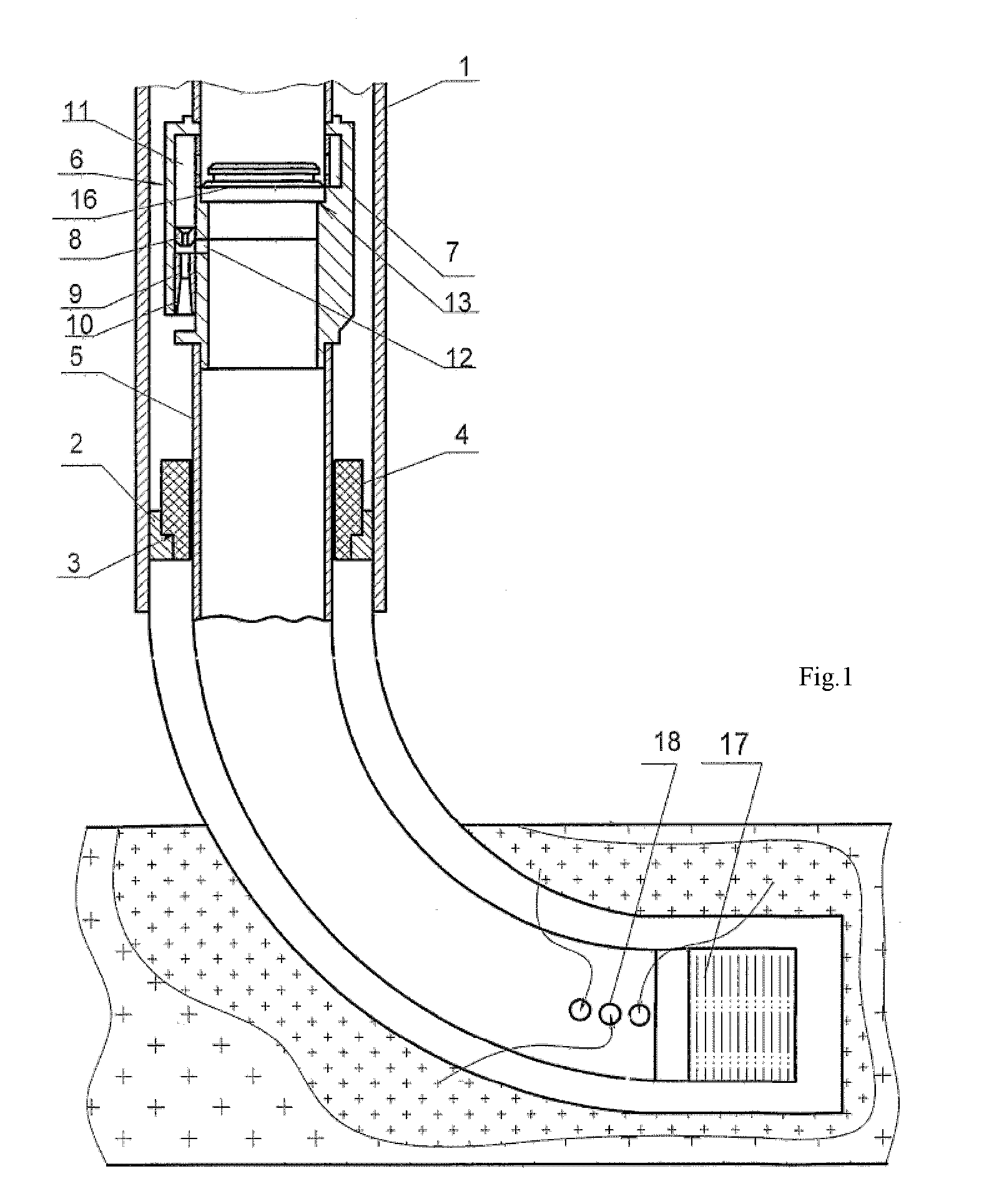
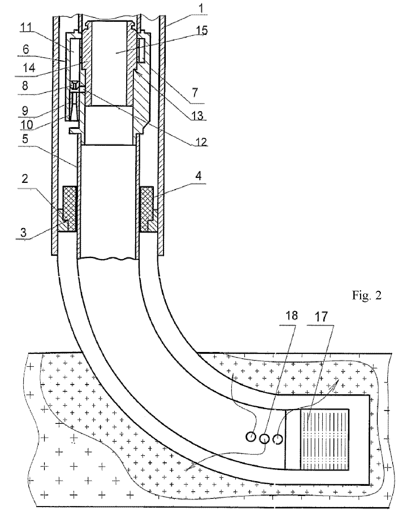
[0019]The claimed device used for carrying out the claimed method comprises the ring 2, which is arranged on the lower section of the casing string 1, with the stepped through channel 3 intended for installing the sealing unit 4, the smooth tubing string 5 with the jet pump 6 installed on it, in the body 7 of the said jet pump the active nozzle 8 and the mixing chamber 9 with a diffuser 10 are arranged as well as the channel 11 for supplying an active medium, the channel 12 for supplying a medium pumped out of a well and the stepped through channel 13 are made, the latter channel being embodied in such a way that it is possible to install therein either a blocking insert 14 having the through channel 15 and serving for closing the channel 11 for supplying an active medium or the depression insert 16 which, when installed, closes the tubing string 5 in its cross-section. The logging device 17 is arranged on the lower end of the tubing string 5, the sealing unit 4 is put on the tubing...


PUM


Abstract

In pumping engineering, the inventive device comprises a ring provided with a sealing unit arranged on a casing string and smooth pipe column. The pump body has a channel supplying an active medium, a channel supplying an active medium pumped out of the well and a stepped through channel such that it is possible to mount therein a blocking insert which closes the active medium supply channel or a depression insert whose mounting cuts off the cross section of the pipe column. A logging device is arranged on the lower end of the pipe column, a sealing unit is put on said pipe column between said logging device and the jet pump such that it is axially offsetable with respect to the pipe column, the lower section of the pipe column above the logging device is embodied such that is perforated.

Description

FIELD OF THE INVENTION[0001]The present invention relates to the field of pumping engineering, particularly to well jet devices for extracting oil from wells.PRIOR ART[0002]A well jet device is known, which comprises a jet pump arranged on a tubing string in a well and a well parameter measuring device arranged below the said jet pump (RU 2089755 C1).[0003]The same source discloses a method of operating the said well jet device, which comprises lowering a tubing string together with a jet pump, a sealing unit and a well parameter measuring device on a logging cable into a well, placing the said measuring device in front of a production formation, and measuring parameters of the latter.[0004]The said device and the method of operating thereof enable to carry out well studies and, due to it, intensify works on studying near-borehole areas in formations.[0005]They, however, do not enable to carry out works on treating the near-borehole area in a formation, which lowers their possibilit...

Claims


Application Information

Patent Timeline
Patent Type & Authority Patents(United States)
IPC IPC(8): E21B47/01E21B49/00F04F5/54F04F5/46
CPCE21B49/00F04F5/464
Inventor KHOMYNETS, ZINOVIY DMITRIEVICH
Owner KHOMYNETS ZINOVIY DMITRIEVICH
Why Eureka
Try Eureka