Phase detection circuit, resolver/digital converter using the circuit, and control system using the converter

a phase detection circuit and digital converter technology, applied in the field of resolver/digital converter, can solve the problems of longer computation time or the need for a circuit capable of high-speed operation, not providing a small-sized and low-cost resolver/digital converter, and not sufficiently satisfying the method disclosed in patent document 1. , to achieve the effect of less affected and noise immunity

Active Publication Date: 2008-11-25
HITACHI ASTEMO LTD
View PDF17 Cites 26 Cited by
  • Summary
  • Abstract
  • Description
  • Claims
  • Application Information

AI Technical Summary

Benefits of technology

[0006]Among those known techniques, the method disclosed in Patent Document 1 is not yet sufficiently satisfactory in point of realizing a smaller size and a lower cost when a resolver / digital converter is manufactured in the IC form. With the disclosed method, precise Sine and Cosine values must be obtained in order to execute computation in a multiplier (control deviation computing unit) 200. Therefore, detailed table values must be stored in a SIN-ROM 60 and a COS-ROM 61. When interpolation is performed to reduce the number of table values, a large amount of computations is required for the interpolation, thus resulting in a longer computation time or the need of a circuit capable of executing high-speed operation. The necessity of using multiplication type D / A converters 51 and 52 in a primary part of the multiplier (control deviation computing unit) 200 is another factor of increasing the circuit scale. For those reasons, the method disclosed in Patent Document 1 can not provide a small-sized and a low-cost resolver / digital converter.
[0007]The method disclosed in Patent Document 2 can provide a smaller circuit scale than the method disclosed in Patent Document 1 and is advantageous in being able to realize a smaller size and a lower cost when the resolver / digital converter is manufactured in the IC form. However, because the method disclosed in Patent Document 2 is more susceptible to the influence of noise, it is not yet sufficiently satisfactory in point of nose immunity during operation of the resolver / digital converter.
[0013]According to the present invention, it is possible to obtain a small-sized and low-cost resolver / digital converter which has noise immunity and is less affected by variation of a center voltage of a resolver signal, i.e., a bias value.

Problems solved by technology

Among those known techniques, the method disclosed in Patent Document 1 is not yet sufficiently satisfactory in point of realizing a smaller size and a lower cost when a resolver / digital converter is manufactured in the IC form.
When interpolation is performed to reduce the number of table values, a large amount of computations is required for the interpolation, thus resulting in a longer computation time or the need of a circuit capable of executing high-speed operation.
For those reasons, the method disclosed in Patent Document 1 can not provide a small-sized and a low-cost resolver / digital converter.
However, because the method disclosed in Patent Document 2 is more susceptible to the influence of noise, it is not yet sufficiently satisfactory in point of nose immunity during operation of the resolver / digital converter.
Therefore, when noise is mixed in the signal at the zero-cross timing, the operation of obtaining the phase and the operation of the resolver / digital converter are affected to a large extent, thus resulting in a possibility that an error occurs in the converted rotational angle.
Further, when a center voltage of a resolver signal, i.e., a bias value, is varied, the zero-cross point is shifted, which may also cause an error in the converted rotational angle.
The known techniques disclosed in Patent Documents 3-6 have problems that the circuit scale of a waveform generation circuit is increased due to the necessity of using two waveform generation circuits and generating a SIN wave.
Patent Document 1 also has a similar problem because the rotational angle is estimated based on the same principle.

Method used


Image

  • Phase detection circuit, resolver/digital converter using the circuit, and control system using the converter
  • Phase detection circuit, resolver/digital converter using the circuit, and control system using the converter
  • Phase detection circuit, resolver/digital converter using the circuit, and control system using the converter

Examples


Embodiment Construction

[0049]An embodiment of the present invention will be described in detail below with reference to the drawings.

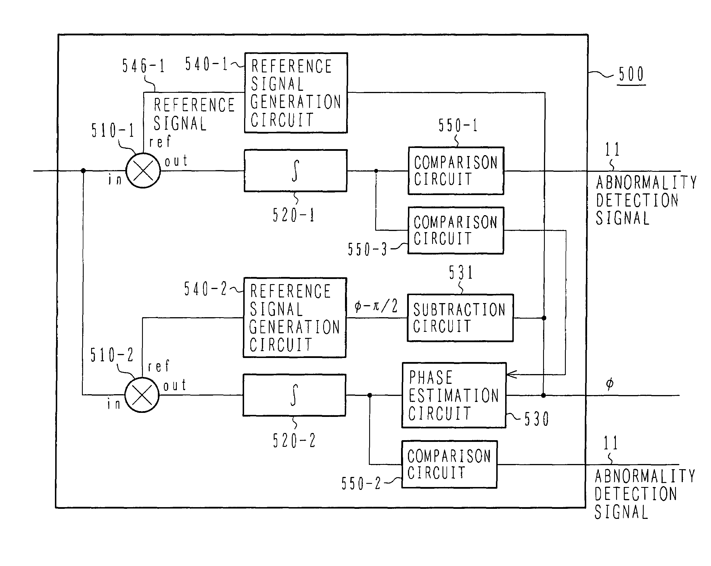
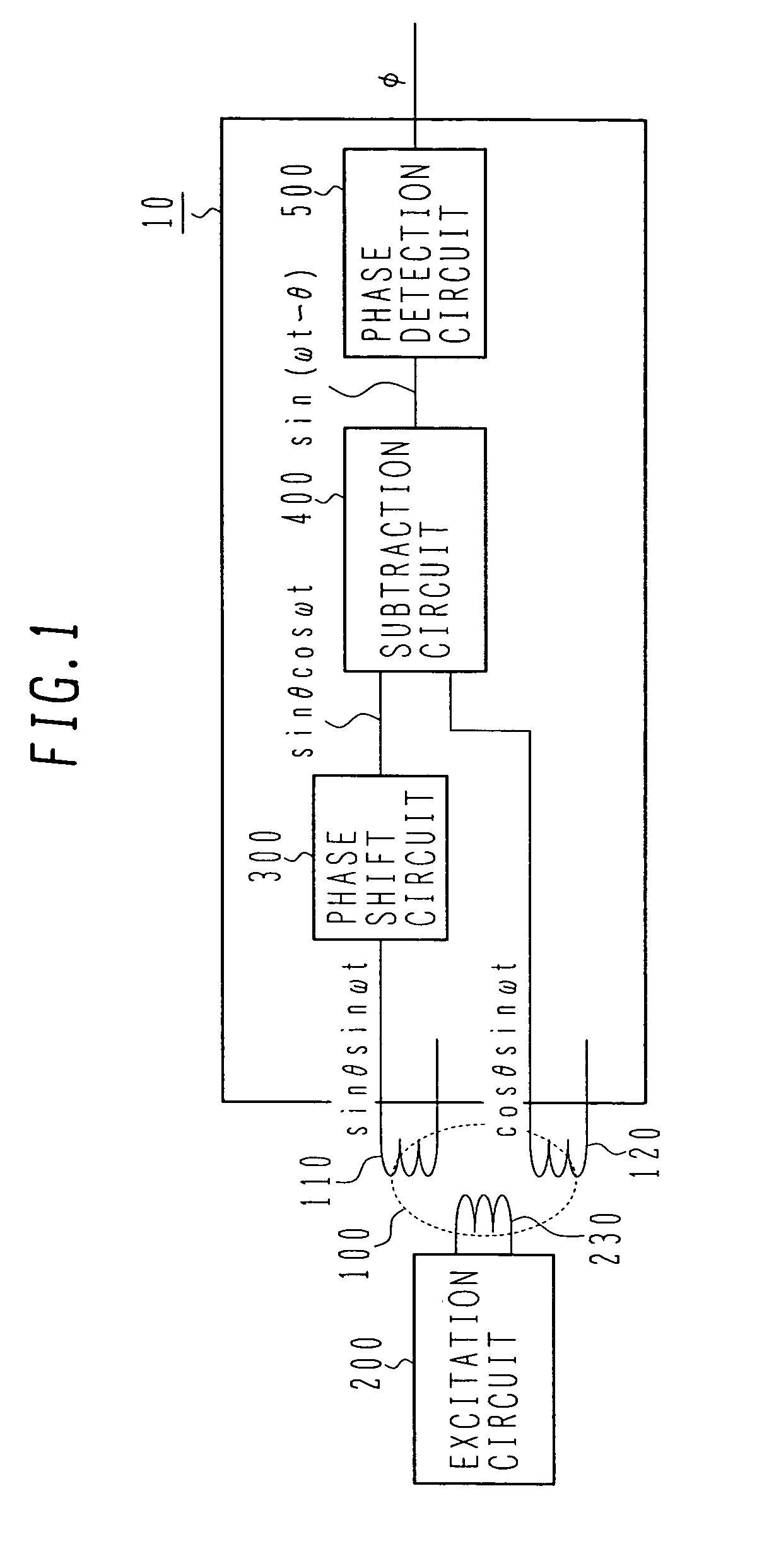
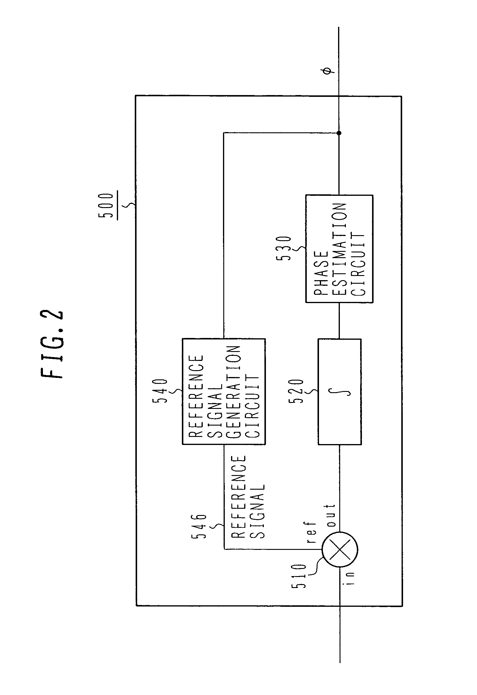
[0050]FIG. 1 is a block diagram showing the entirety of a resolver / digital converter according to the present invention. An excitation circuit 200 outputs an excitation signal 230 to a resolver 100. A SIN output 110 and a COS output 120 of the resolver 100 are inputted to a resolver / digital converter 10. A phase shift circuit 300 delays the phase of the SIN output 110 by 90°, and a subtraction circuit 400 subtracts the delayed SIN output 110 from the COS output 120. A phase detection circuit 500 detects the phase of the subtraction result and outputs an estimated value φ of a rotational angle θ.

[0051]Here, the SIN output 110 and the COS output 120 of the resolver 100 are expressed respectively by sin θ sin ωt and cos θ sin ωt (θ: rotational angle (electrical angle) of the resolver), ω: angular velocity (2πf, f: frequency of the resolver excitation signal) of the resolver exc...


PUM


Abstract

A small-sized and low-cost phase detection circuit which has improved noise immunity. The phase detection circuit comprises a multiplier for multiplying an input signal by a reference signal and outputting a first signal, an integration circuit for integrating the first signal and outputting a second signal, a phase estimation circuit for estimating phase information based on the second signal, and a reference signal generation circuit for generating the reference signal based on the estimated phase information. Since the phase is detected based on information representing an entire waveform, the influence of local noise can be diluted and noise immunity can be improved.

Description

BACKGROUND OF THE INVENTION[0001]1. Field of the Invention[0002]The present invention relates to a resolver / digital converter, and more particularly to a small-sized and low-cost resolver / digital converter having noise immunity.[0003]2. Description of the Related Art[0004]In a servo control system, a rotational angle sensor is required to detect a rotational angle and to perform feedback control. In control of a brushless motor, a rotational angle sensor is also required because of the necessity of supplying a current to a motor coil depending on a motor rotational angle. Thus, the rotational angle sensor is required in not only the servo control system, but also in other systems. As the rotational angle sensor, a resolver has hitherto been widely used from the advantageous features of robustness and environment resistance which are attributable to its simple construction.[0005]Further, a resolver / digital converter has been developed which is used to convert a signal from the resolv...

Claims


Application Information

Patent Timeline
Patent Type & Authority Patents(United States)
IPC IPC(8): H02P23/00G01B7/00G01B7/30G01D5/20G01D5/245
CPCG01D5/2073H03M1/485
Inventor KANEKAWA, NOBUYASUSASAKI, SHOJIOYAMA, KATSUYAKOSEKI, TOMONOBU
Owner HITACHI ASTEMO LTD
Why Eureka
Try Eureka