System and method for reducing ZAP time and track squeeze in a data storage device

a data storage device and zap time technology, applied in the field of disk drive data storage systems, can solve the problems of writing-in errors, head following, writing-in errors, etc., and achieve the effect of reducing the overall time required and mitigating ac track squeeze issues

Active Publication Date: 2008-11-25
SEAGATE TECH LLC
View PDF23 Cites 40 Cited by
  • Summary
  • Abstract
  • Description
  • Claims
  • Application Information

AI Technical Summary

Benefits of technology

[0011]The present invention relates to a method and apparatus for compensating for errors in servo systems. An improved zero acceleration path (ZAP) correction technique is provided, wherein selected tracks of a data storage device are used for ZAP processing in order to reduce the overall time required to perform error compensation for a storage device. For a given selected track to be ZAPed, where profiles used to position a head over the selected track are modified or ZAPed, track profiles of adjoining tracks are used in addition to the track profile of the selected track as part of the ZAP correction determination for the selected track. Using adjacent track profiles as part of the ZAP correction determination assists in mitigating AC track squeeze issues that would otherwise occur when performing selective track ZAPing.

Problems solved by technology

However, two types of errors prevent heads from following this ideal path.
The first type of error is a written-in error that arises during the creation of the servo fields.
Written-in errors occur because the write head used to produce the servo fields does not always follow a perfectly circular path due to, for example, unpredictable pressure effects on the write head from the aerodynamics of its flight over the disc, and from vibrations in the gimbal used to support the head.
Track following errors arise as a head attempts to follow the path defined by the servo fields.
The track following errors can be caused by the same aerodynamic and vibrational effects that create written-in errors.
In addition, track following errors can arise because the servo system is unable to respond fast enough to high frequency changes in the path defined by the servo fields.
As track densities increase, these repeatable runout errors begin to limit the track pitch.
Specifically, variations between the ideal track path and the actual track path created by the servo fields can result in a track interfering with or squeezing an adjacent track.
Vibrations during the servo track writing process can cause track squeeze.
Track squeeze has to be accounted for as an uncertainty when specifying the track spacing of a disc drive, and therefore, track squeeze limits the maximum achievable track density.
Track misregistration can also be caused by media imperfections.
This, in turn, results in a position measurement error and track misregistration.
Because of various disturbances occurring during the servo write process and media imperfections, the track center is not smooth.
A disc drive actuator typically would have difficulty following this path.
However, as densities of disc drives increase, the amount of time required to perform conventional ZAP methods similarly increases.

Method used


Image

  • System and method for reducing ZAP time and track squeeze in a data storage device
  • System and method for reducing ZAP time and track squeeze in a data storage device
  • System and method for reducing ZAP time and track squeeze in a data storage device

Examples


Embodiment Construction

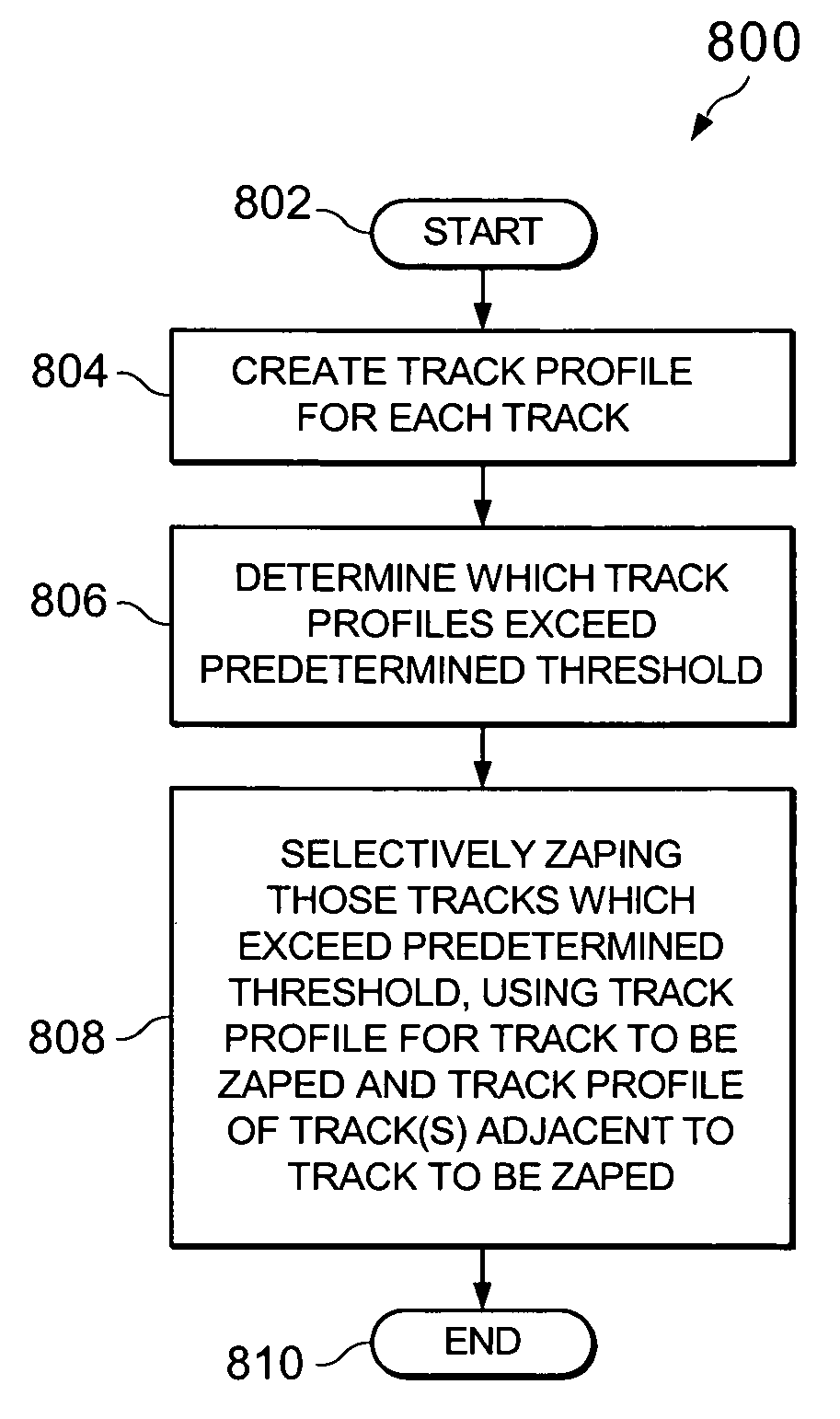
[0021]The amount of time required by conventional ZAP methods used in reducing repeatable runout errors (RRO) in a data storage device is steadily increasing as data storage densities are increasing. One way of reducing the ZAP time is by using a technique herein described as ZAP-By-Exception (ZBE), which selectively ZAPs those tracks that have large PES and tend to cause track encroachment problems. In one ZBE embodiment, ZAP is applied to every track in the outside diameter (OD) zones since PES RRO is typically large at almost every track in such OD zone. In other zones, the ZAP is activated only on those tracks having a large PES or large mean of PES. In this later situation, ZAPing the track may bring down the PES RRO, and the 3-sigma of AC track squeeze value (AC SQ). However, at certain sectors, the ZBE processing could actually worsen the AC SQ. The following example will illustrate this point.

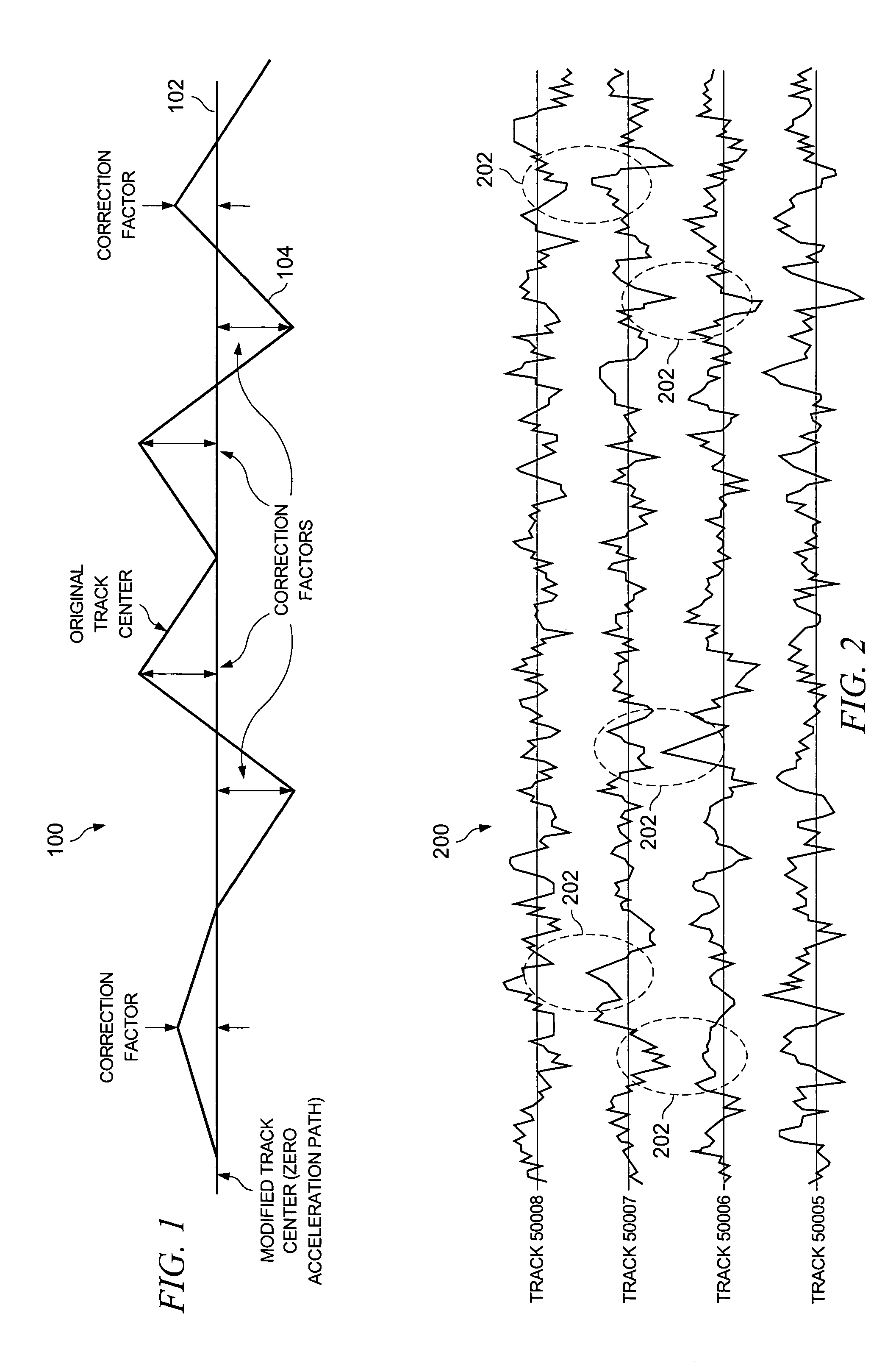
[0022]Referring now to FIG. 2, there is shown at 200 an example where ZAP compensat...


PUM

PropertyMeasurementUnit
thresholdaaaaaaaaaa
pressureaaaaaaaaaa
aerodynamicaaaaaaaaaa

Abstract

A method and apparatus for compensating for errors in servo systems. An improved zero acceleration path (ZAP) correction technique is provided, wherein selected tracks of a data storage device are used for ZAP processing in order to reduce the overall time required to perform error compensation for a storage device. For a given selected track to be ZAPed, track profiles of adjoining tracks are used in addition to the track profile of the selected track as part of the ZAP correction determination for the selected track. Using adjacent track profiles as part of the ZAP correction determination assists in mitigating AC track squeeze issues that would otherwise occur when performing selective track ZAPing.

Description

FIELD OF THE INVENTION[0001]The present invention relates generally to disc drive data storage systems. More particularly, the present invention relates to compensation for errors in servo systems.BACKGROUND OF THE INVENTION[0002]Disc drives read and write information along concentric tracks formed on discs. To locate a particular track on a disc, disc drives typically use embedded servo fields on the disc. These embedded fields are utilized by a servo subsystem to position a head over a particular track. The servo fields are written onto the disc when the disc drive is manufactured and are thereafter read by the disc drive to determine position.[0003]Ideally, a head following the center of a track moves along a perfectly circular path around the disc. However, two types of errors prevent heads from following this ideal path. The first type of error is a written-in error that arises during the creation of the servo fields. Written-in errors occur because the write head used to produ...

Claims


Application Information

Patent Timeline
Patent Type & Authority Patents(United States)
IPC IPC(8): G11B5/596
CPCG11B5/59605G11B19/045
Inventor LIU, XIONGBI, QIANGPANG, TZEMING JIMMYLIM, CHOONKIAT
Owner SEAGATE TECH LLC
Why Eureka
Try Eureka