
System and method for sensing torque on a rotating shaft

a technology of rotating shaft and torque, applied in the field of optical sensors, can solve the problems of inability to obtain torque data from light weight sensing systems, inability to achieve the effect of facilitating subsequent control actions, and inability to detect the torque of rotating shafts driving loads

Inactive Publication Date: 2008-12-02
ROCKWELL AUTOMATION TECH
View PDF48 Cites 11 Cited by
  • Summary
  • Abstract
  • Description
  • Claims
  • Application Information

AI Technical Summary

Benefits of technology

The system provides comprehensive analysis of torque, strain, and misalignment, enabling predictive maintenance, automatic correction, and improved reliability in rotating machinery, with high-frequency load sensing and lightweight, cost-effective implementation.

Problems solved by technology

Robust, affordable, lightweight sensing systems for obtaining data regarding a moving or rotating shaft (specifically torque), however, are presently non-existent.
Rotating shafts driving a load are susceptible to torsional strain.
Continuous strain on the shaft will eventually result in machine inefficiency and / or shaft deformation and / or breakage (e.g., shaft cracking).
Dynamic torque (strain) fluctuations can cause mechanical and fatigue damage as well as accelerate machine failure.
However, conventional torque sensors are large, costly, heavy, failure prone, and provide limited dynamic signal (bandwidth).
However, providing suitable signal amplification and signal analysis is also impractical due to size, weight, reliability, cost, and performance factors.
Furthermore, the conventional shaft torque sensing system in the example above would cost at least five thousand dollars, be susceptible to failure due to shock loads, and take up valuable aircraft space and payload capacity.
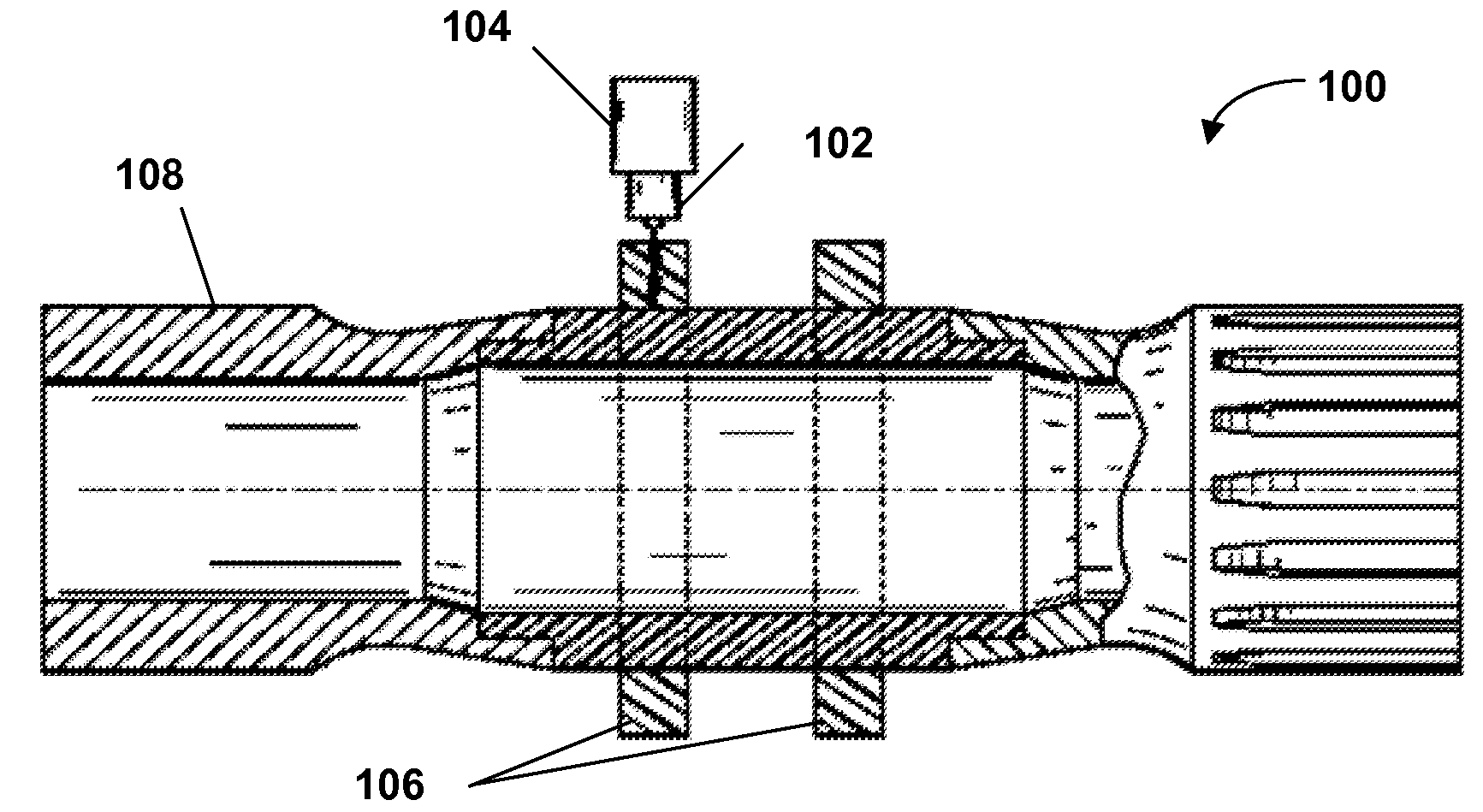
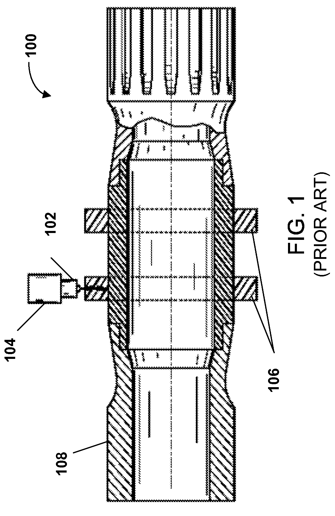
Conventional sensing systems that consider angular displacement difference between two ends of a rotating shaft typically involve costly and complex optics and mechanical interconnect equipment.
Additionally, rotating shafts are prone to misalignment when two or more shafts are employed and coupled together.
For example, misalignment between a motor shaft and a pump shaft is a significant and prevalent cause of premature bearing and seal failure, which often cause motor failures and motor-pump system failures.
Misalignment can also cause accelerated wear on couplings, mountings, piping, and increased heating and energy loss.
Conventional systems typically align coupled shafts utilizing mechanical gauges and shims; however, these techniques are not precise.
Alternative techniques employ laser alignment, but these systems are typically costly, time consuming, and are only performed while the machinery is not operating.
Effects such as thermal expansion and dynamic shaft loading due to mechanical or magnetic fields can cause a system aligned while at rest to become misaligned when functioning at operating temperatures with loads.
Prior art methods can also have a limited ability to verify the integrity of composite joints.
Prior art techniques (e.g., acoustic, IR) are difficult, costly and time consuming.
Lastly, optical sensing systems can provide high frequency torque signals unobtainable with conventional torque sensor(s).
In particular, the prior art systems and methods fail to establish whether rotating shafts are in alignment and the degree of misalignment, and further lack the ability to perform dynamical alignment.

Method used


Image

  • System and method for sensing torque on a rotating shaft
  • System and method for sensing torque on a rotating shaft
  • System and method for sensing torque on a rotating shaft

Examples


Embodiment Construction

[0048]The present invention is now described with reference to the drawings, wherein like reference numerals are used to refer to like elements throughout. In the following description, for purposes of explanation, numerous specific details are set forth in order to provide a thorough understanding of the present invention. It may be evident, however, that the present invention may be practiced without these specific details. In other instances, well-known structures and devices are shown in block diagram form in order to facilitate describing the present invention.

[0049]As used in this application, the terms “component” or “system” are intended to refer to a computer-related entity, either hardware, a combination of hardware and software, software, or software in execution. For example, a computer component can be (but is not limited to) a process running on a processor, a processor, an object, an executable, a thread of execution, a program, and / or a computer. By way of illustrati...


PUM

PropertyMeasurementUnit
angleaaaaaaaaaa
frequencyaaaaaaaaaa
opticalaaaaaaaaaa

Abstract

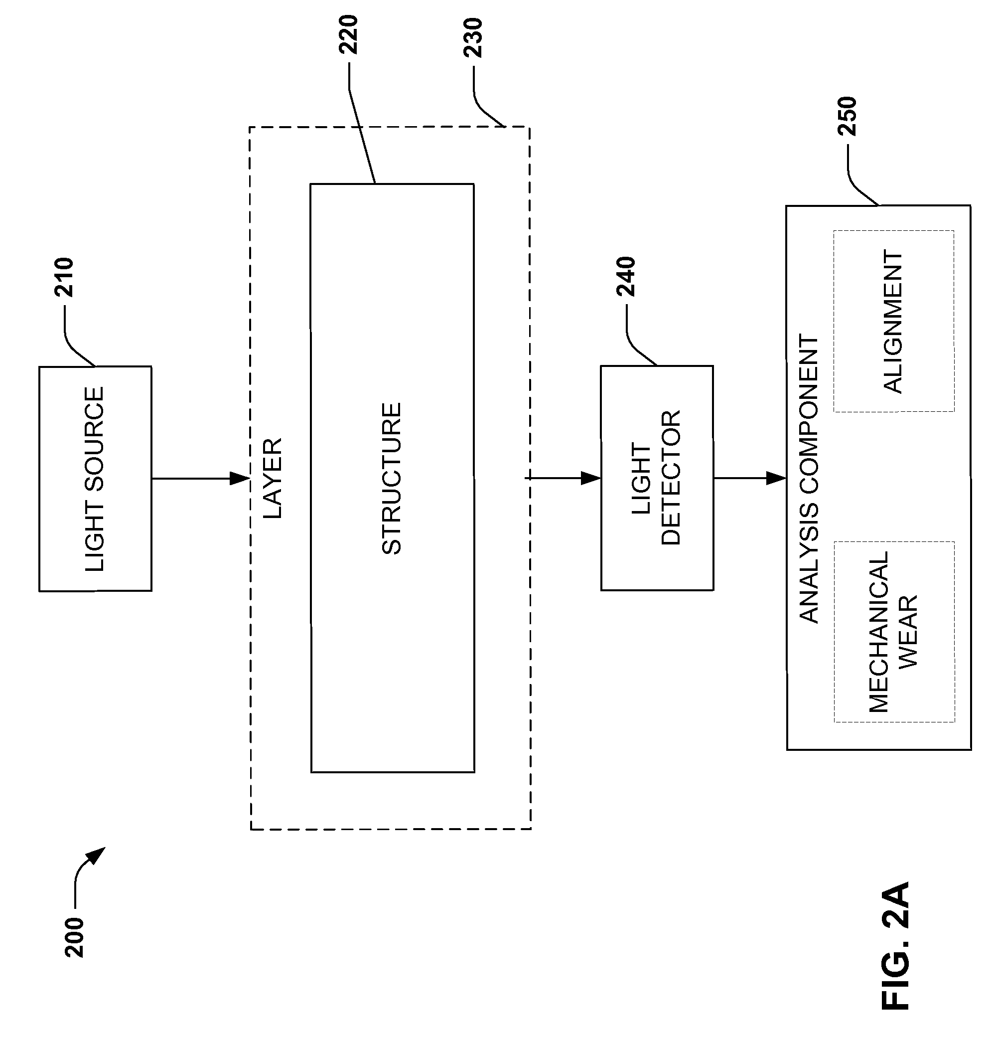
A system and method relating to the measuring of torque in a rotating shaft is provided. An optical torque sensing system comprises a rotating shaft, wherein a sleeve of photo-elastic material overlays a portion of the shaft. A light emitting component delivers light into the photo-elastic material, wherein the light delivered by the light emitting component is directed through the photo-elastic material along an axis of the rotating shaft. A capturing component captures the light that exits the photo-elastic material. The exiting light comprises fringe pattern data, and a computing system computes torsion strain of the shaft based at least in part on the fringe pattern information

Description

CROSS-REFERENCE TO RELATED APPLICATIONS[0001]This application is a divisional of U.S. patent application Ser. No. 11 / 203,790, filed Aug. 15, 2005, and entitled, “SYSTEM AND METHOD FOR SENSING TORQUE ON A ROTATING SHAFT”, which is a continuation of U.S. patent application Ser. No. 10 / 674,967, filed Sep. 30, 2003, and entitled, “SYSTEM AND METHOD FOR SENSING TORQUE ON A ROTATING SHAFT”, which is a Continuation-in-Part of U.S. patent application Ser. No. 10 / 409,894, filed Apr. 9, 2003, and entitled, “SYSTEM AND METHOD FOR SENSING TORQUE ON A ROTATING SHAFT”, which is an application claiming benefit under 35 U.S.C. § 119(e) of U.S. Provisional Patent Application Ser. No. 60 / 371,104, filed Apr. 9, 2002, and entitled, “SYSTEMS AND METHODOLOGIES FOR ENHANCING MACHINE RELIABILITY.” The entireties of these aforementioned applications are incorporated herein by reference.TECHNICAL FIELD[0002]The present invention generally relates to optical sensors employed in conjunction with sensing a phot...

Claims


Application Information

Patent Timeline
Patent Type & Authority Patents(United States)
IPC IPC(8): G01L1/24
CPCG01L1/241G01L3/12
Inventor DISCENZO, FREDERICK M.
Owner ROCKWELL AUTOMATION TECH
Learn More