Portable power planer

a power planer and portable technology, applied in the field of portable power tools, can solve the problems of largely inadequate portable planing machines

Inactive Publication Date: 2008-12-02
BLACK & DECKER INC
View PDF21 Cites 4 Cited by
  • Summary
  • Abstract
  • Description
  • Claims
  • Application Information

AI Technical Summary

Problems solved by technology

While such designs have proven to be acceptable for relatively large planing machines which are repositioned on a relatively infrequent basis, they have largely been inadequate for portable planing machines, due to their weight.

Method used


Image

  • Portable power planer
  • Portable power planer
  • Portable power planer

Examples


Embodiment Construction

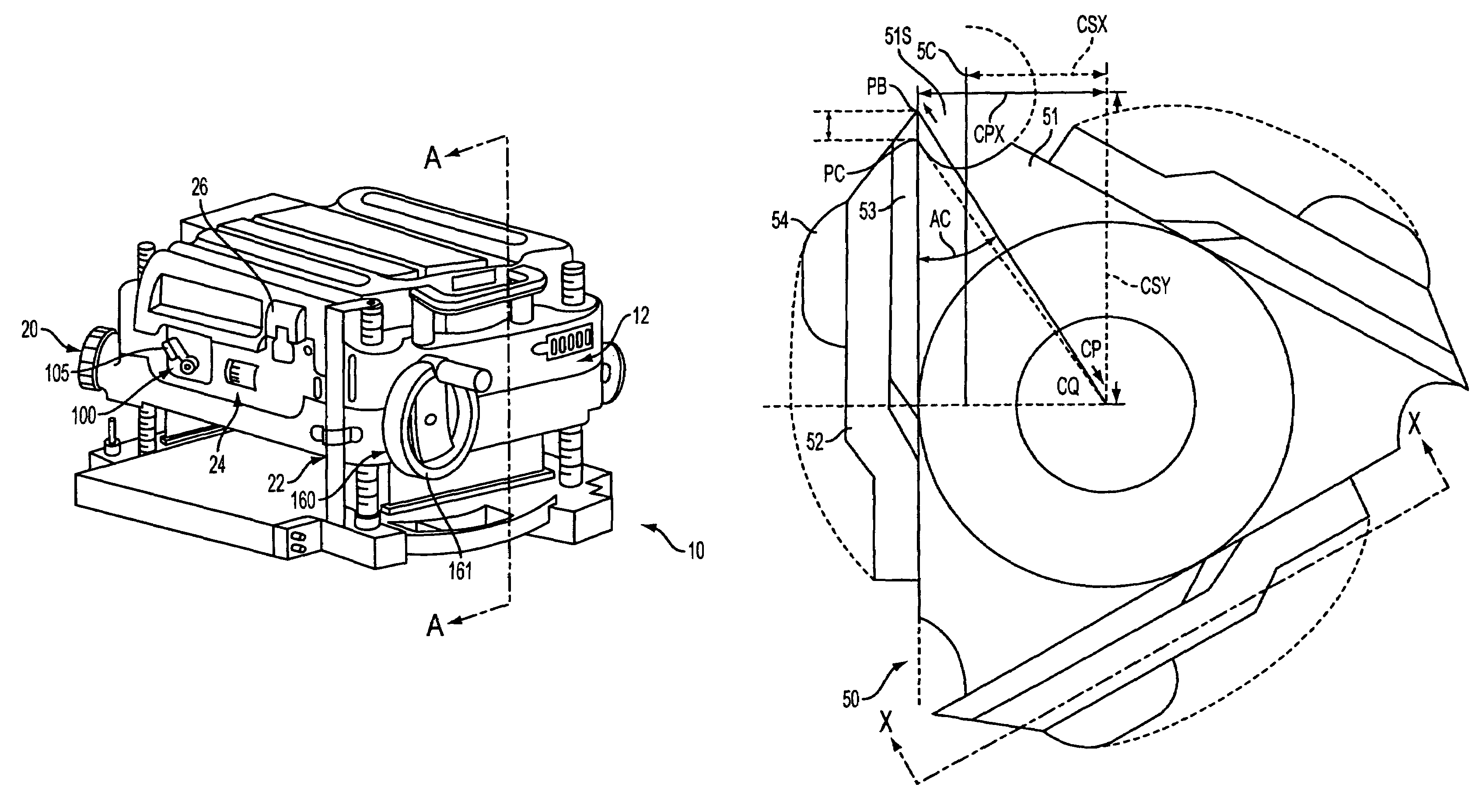
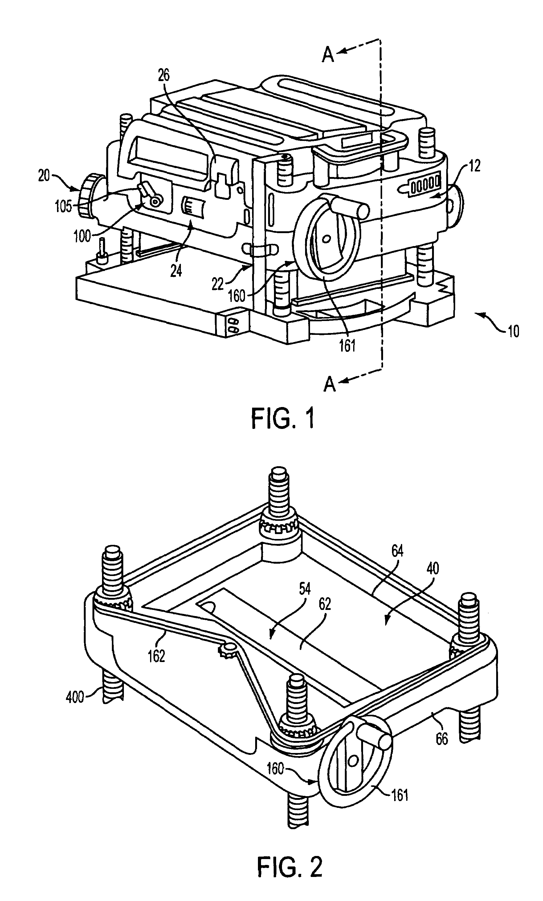
[0022]With reference to FIG. 1 of the drawings, a planer mechanism constructed in accordance with the teachings of the present invention is generally indicated by reference numeral 10. The teachings of U.S. Pat. No. 6,601,621 are fully incorporated herein by reference.

[0023]The planer mechanism 10 preferably includes a planer carriage assembly 12, a base assembly 14, a planer carriage elevation mechanism 160, a carriage height setting mechanism 20, a height scale mechanism 22, a material removal gauge 24, an on / off switch 26, and a speed selection assembly 100.

[0024]As further explained below, the planer carriage elevation mechanism 160 preferably includes a hand crank 161. Preferably hand crank 161 is disposed on planer mechanism 10 so that it is substantially, if not completely, in the front half of planer mechanism 10, i.e., in front of a center plane A-A dividing the planer mechanism 10 in half.

[0025]As further explained below, the speed selection assembly 100 has a selector han...


PUM


Abstract

A portable power planer for planing the top surface of a workpiece. The portable power planer includes a base assembly, a carriage assembly disposed above the base assembly, the carriage assembly includes a cutterhead assembly, the carriage assembly being vertically movable to change distance between the base assembly and the carriage assembly, a hand crank attached to the carriage assembly for changing the distance between the base assembly and the carriage assembly, a material removal gauge disposed on the carriage assembly, a switch disposed on the carriage assembly, and a height scale disposed on the base assembly, wherein the material removal gauge, the switch and the height scale are on the front side of the power planer, and the hand crank is substantially on the front half of the power planer.

Description

CROSS-REFERENCE TO RELATED APPLICATIONS[0001]This application is a continuation-in-part of U.S. patent application Ser. No. 10 / 428,385, filed on May 2, 2003, now U.S. Pat. No. 6,708,774, which is in turn a continuation of U.S. patent application Ser. No. 10 / 124,746, filed on Apr. 17, 2002, now U.S. Pat. No. 6,601,621, which in turn claims priority to U.S. Provisional Application Ser. No. 60 / 284,486, filed on Apr. 18, 2001, now abandoned.FIELD OF THE INVENTION[0002]The present invention generally relates improvements in portable power tools, and more specifically to improvements that are particularly well suited for use with wood working power tools such as portable power planers.BACKGROUND OF THE INVENTION[0003]Various power tools are used in woodworking in an effort to efficiently and accurately form workpieces to desired dimensions and with a desired surface finish. As is widely known, planing machines are often used for surface planing of wooden boards. A conventional planing mac...

Claims


Application Information

Patent Timeline
Patent Type & Authority Patents(United States)
IPC IPC(8): B27C1/00B23Q11/00B23Q17/22B27C1/04B27C1/14B27G13/04
CPCB23Q11/0046B23Q17/22B27C1/04B27C1/14B27G13/04
Inventor WIXEY, BARRYWELSH, ROBERT P.WIKLE, DAVID L.LIN, JYH CHERNGCHANG, LEOCHI, CHIN LONG
Owner BLACK & DECKER INC
Why Eureka
Try Eureka