Reduction of turbulence within printing region of inkjet printer heads

a printing region and inkjet printer technology, applied in the field of inkjet printers, can solve the problems of affecting the proper functioning of the print head, the inability of the inkjet printing system to work normally, and the prior art has not addressed the issue of non-conformity, so as to reduce the turbulence of the air moving through the inkjet print head enclosure and reduce the artifacts of images

Inactive Publication Date: 2008-12-02
EASTMAN KODAK CO
View PDF13 Cites 11 Cited by
  • Summary
  • Abstract
  • Description
  • Claims
  • Application Information

AI Technical Summary

Benefits of technology

[0007]In accordance with a feature of the present invention, it has been found that the turbulence of the air moved through an inkjet print head enclosure can be reduced before reaching the printing region by positioning a HEPA filtration system between an air inlet opening in the enclosure and the printing region.
[0008]According to another feature of the present invention, a method is provided for reducing artifacts in images produced by an inkjet print head. The method includes moving turbulent air through an air path from an air source toward the printing region and positioning a HEPA filtration system in the air path such that only laminar air flow is introduced to the printing region.

Problems solved by technology

Ink jet printing systems are susceptible to turbulent air streams and paper dust, contamination that affect the proper functioning of the print head.
While these structures have greatly reduced particle-based malfunctions, the prior art has not addressed the issue of non-straight ink droplet trajectories caused by turbulent air streams between print head nozzle openings and the print media (herein referred to as the “printing region”).
When turbulent air streams occur within the printing region, the affected jet causes misregistration of droplets and less than desired print quality.

Method used


Image

  • Reduction of turbulence within printing region of inkjet printer heads
  • Reduction of turbulence within printing region of inkjet printer heads
  • Reduction of turbulence within printing region of inkjet printer heads

Examples


Embodiment Construction

[0016]The present description will be directed in particular to elements forming part of, or cooperating more directly with, apparatus in accordance with the present invention. It is to be understood that elements not specifically shown or described may take various forms well known to those skilled in the art.

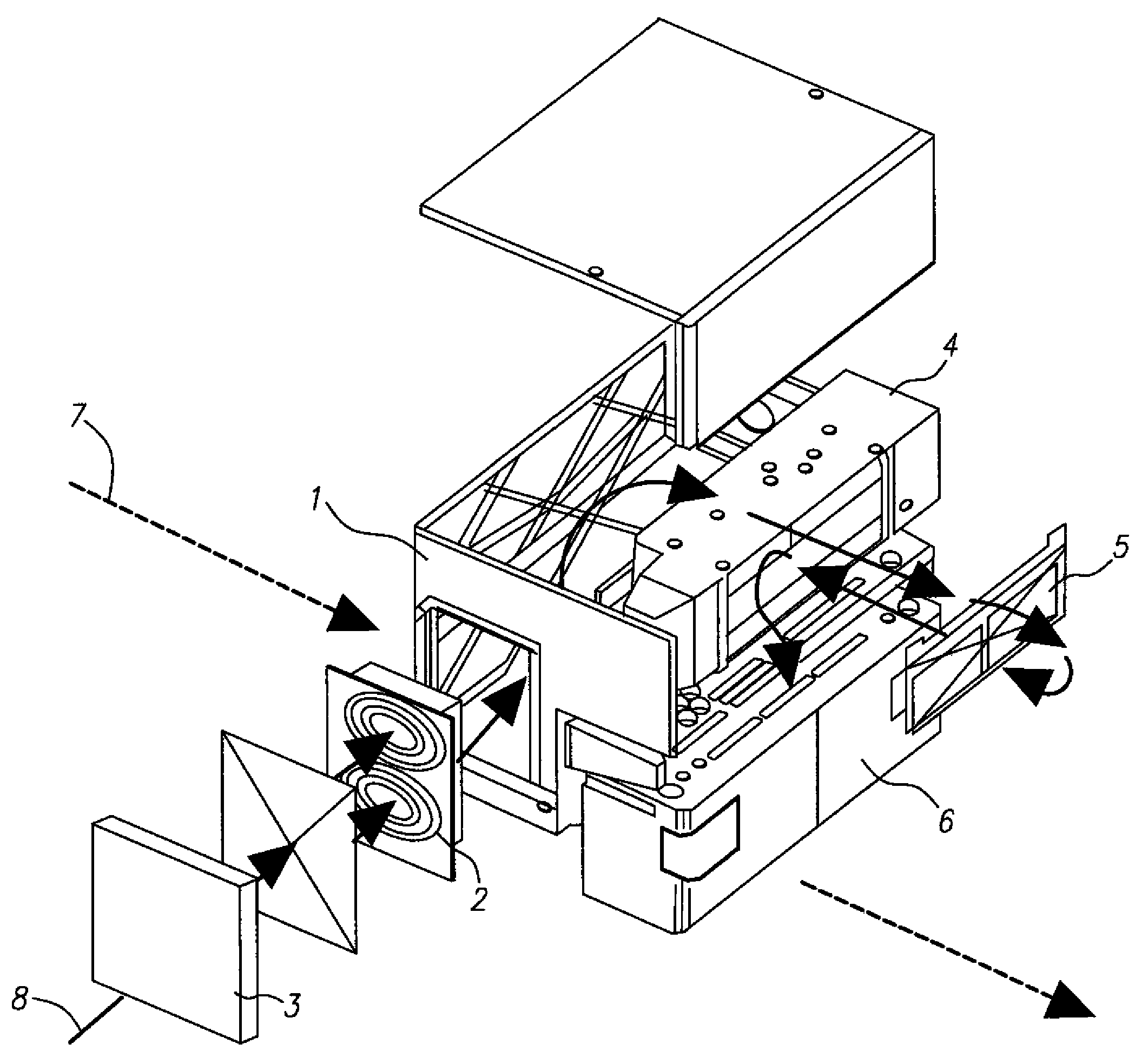
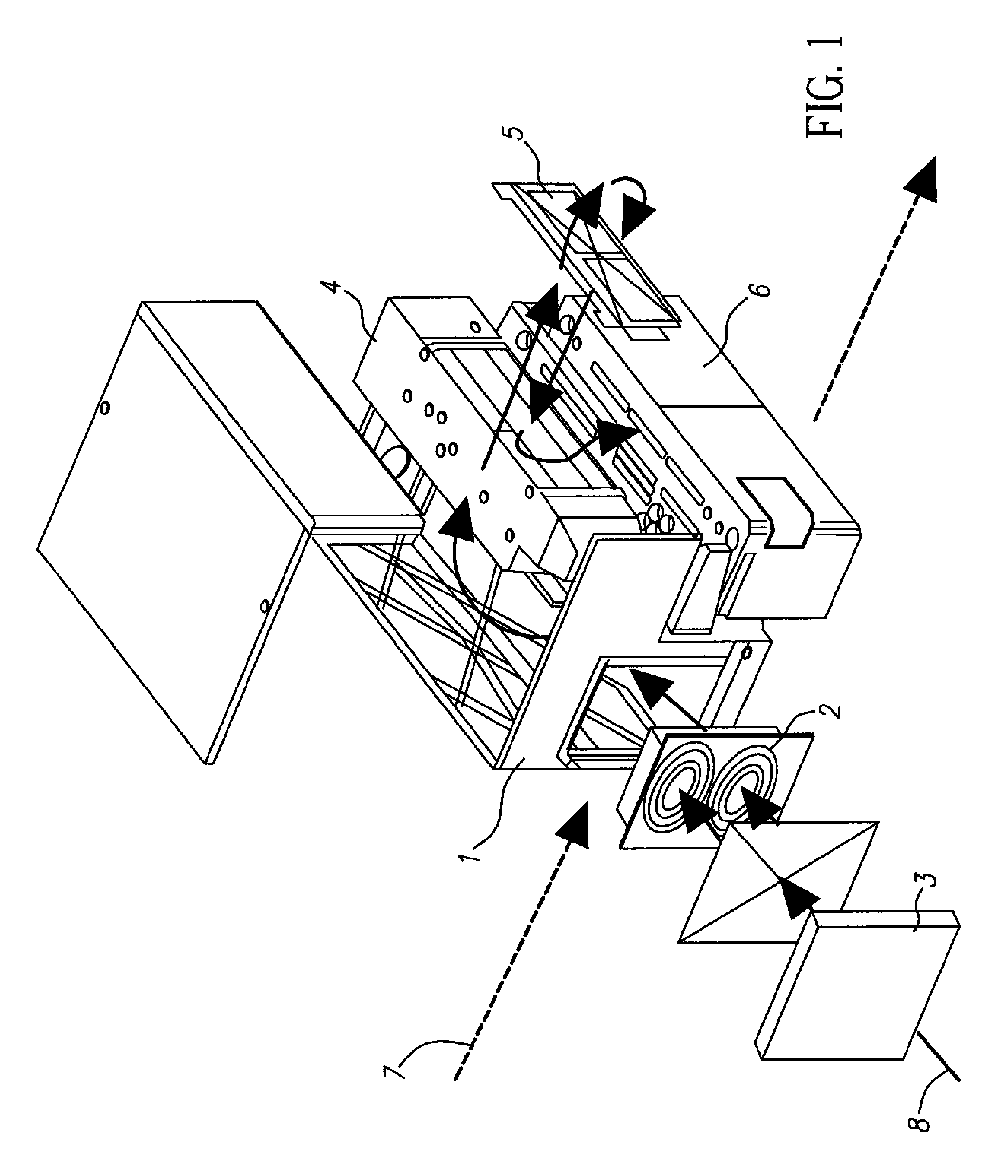
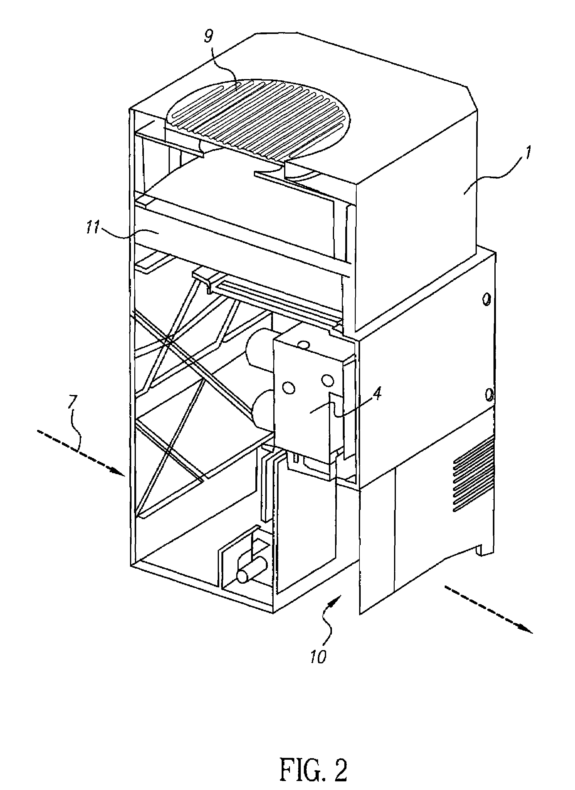
[0017]FIG. 2 illustrates a print head assembly according to a preferred embodiment of the present invention. Reference numerals that appear both in prior art FIG. 1 and in FIG. 2 refer to structure that is similar in function, but not necessarily identical in structure. For example, reference numeral 1 identifies a print head interface controller enclosure 1 in FIG. 2 that has the same function as print head interface controller configuration 1 of FIG. 1, but clearly differs in configuration. The same is true of manifold 4, which precedes the region 10 for placement of the print head (the print head has not been illustrated in FIG. 2 for clarity). As in the prior art, the mani...


PUM


Abstract

The turbulence of the air moved through an inkjet print head enclosure is reduced before reaching the printing region between the print head and a print medium by positioning a HEPA filtration system between an air inlet opening in the enclosure and the print head. Turbulence is removed from air moved through the air path by HEPA filtration of the air being drawn into the print head enclosure before reaching the printing region.

Description

FIELD OF THE INVENTION[0001]The present invention relates to the field of ink jet printers. More specifically, the invention relates to methods of providing laminar air within a printing region of such printers so that printed artifacts are reduced.BACKGROUND OF THE INVENTION[0002]Ink jet printing systems are susceptible to turbulent air streams and paper dust, contamination that affect the proper functioning of the print head. Several methods of protecting the regions surrounding the print head from contamination have been established, such as by enclosing the print head and filling the enclosure with filtered air under positive pressure.[0003]FIG. 1 is an example of such a prior art system, wherein a print head assembly is provided with a print head interface controller enclosure 1 having an air inlet fan 2 adapted to force air into enclosure 1 through a replaceable air inlet filter 3. The filter reduces the amount of foreign debris from the internal components of the print head. ...

Claims


Application Information

Patent Timeline
Patent Type & Authority Patents(United States)
IPC IPC(8): B41J29/13
CPCB41J29/13B41J29/377
Inventor MORRIS, BRIAN G.SIMON, ROBERT J.
Owner EASTMAN KODAK CO
Why Eureka
Try Eureka