Magnetic spacer

a spacer and magnetic technology, applied in the field of spacers, can solve the problems of not being practical, still some problems to be solved, and consumers still need uninterrupted technology improvement, so as to prevent slipping

Active Publication Date: 2008-12-02
HIWIN TECH
View PDF9 Cites 9 Cited by
  • Summary
  • Abstract
  • Description
  • Claims
  • Application Information

AI Technical Summary

Benefits of technology

[0014]The primary objective of the present invention is to provide a magnetic spacer that can be prevented from tipping over.
[0017]The spacer of the present invention not only can be adsorbed on the balls, but also utilizes the different specific gravity material of the magnetic filler to shift the center of gravity of the spacer, keeping the magnetic filler outward during operation, thus achieving the effect of preventing tipping over, and enabling the spacer to stand up automatically under the effect of gravity and centrifugal force.
[0018]The aforesaid gravity and centrifugal force are called “acceleration force”. Gravity is a gravity acceleration force applied on the spacer by the earth. The centrifugal force is an inertial force caused by the rotation of the spacer, which is the counterforce to the acceleration centripetal force. The magnetic force is a permanent force caused in response to change in atom arrangement (the indirect magnetic force can prevent the elements from magnetization). All these three forces are force acting at a distance, therefore, when different parts of the spacer have different specific gravities, and with the aid of the indirect magnetic force, the spacer will be inclined toward the relatively heavier side along with the centrifugal force (when the spacer rotates around the screw shaft, the resultant centrifugal force will keep the center of gravity side of the spacer facing outward). Plus the influence of the magnetic force, the spacer of the present invention can be reliably prevented from tipping over.

Problems solved by technology

Although the technology for linear transmission element is developing fast, consumers still need the technology to be improved uninterruptedly.
Therefore, there are still some problems to be solved.
Most of the spacer 11 products are required to be miniaturized, unitary and made of single material, however, they not practical because of the following reasons:
However, if the reserved intervals between the balls 10 are gathered together, it will form a space that is large enough to make the spacers 11 fall down easily, and the spacers 11 fell down on the surface of the screw shaft 16 will interfere the operation of the balls 10.
Therefore, the spacers 11 are impossible to stand up automatically, and this will probably cause failure of the whole ball screw system.
In use, the non-uniform rotating speed of the balls 10 also will result in an occurrence of an overlarge distance between the balls 10, making it impossible to hold the spacers 11 firmly.
Therefore, the spacers 11 are likely to tip over or to rub against the helical grooves of the screw shaft and the nut, adversely affecting the service life and the efficiency of the ball screw and the linear guideway.
However, when the reserved intervals between the balls 10 are gathered together, the spacers 11 also will fall down easily without the possibility of standing up again (as shown in FIG. 5), thus causing failure of the whole ball screw system.

Method used


Image

  • Magnetic spacer
  • Magnetic spacer
  • Magnetic spacer

Examples


first embodiment

[0038]For a better understanding of the first embodiment, its operation and function, reference should be made to FIG. 8.

[0039]Since the magnetic filler 40 is filled in the receiving space 32 of the spacers 30, and the balls 20 are magnetic conductive, an indirect magnetic attractive force will be produced between the filler 40 and the respective balls 20, and the strongest magnetic field is located on the line connecting the centers of the respective balls 20. However, the contacting point of the spacer 30 and the ball 20 is located at either side of the arc groove 31 (normally, the arc groove is of Gothic type), and thus the ball 20 will not directly contact the coating layer covering the magnetic filler 40, preventing abrasion of the magnetic spacers 30.

[0040]If the reserved intervals between the whole array of the balls 20 are gathered together in the helical groove of the screw shaft 50, each of the magnetic spacers 30 will be adsorbed on a side of the respective balls 20 by th...

second embodiment

[0041]Referring to FIG. 9, which shows the present invention, and the structure of this embodiment is explained as follows:

[0042]An arc groove 31 is formed in each side of the respective spacers 30, and an annular receiving space 60 is defined in each of the spacers 30 for accommodation of magnetic filler 40. Such annular receiving space 60 not only increases the filling amount of the magnetic filler 40 while reducing the intervals, but also enables spacers 30 to be adsorbed on the balls 20 more stably and effectively.

third embodiment

[0043]Referring then to FIG. 10, which shows the present invention, and the structure of this embodiment is explained as follows:

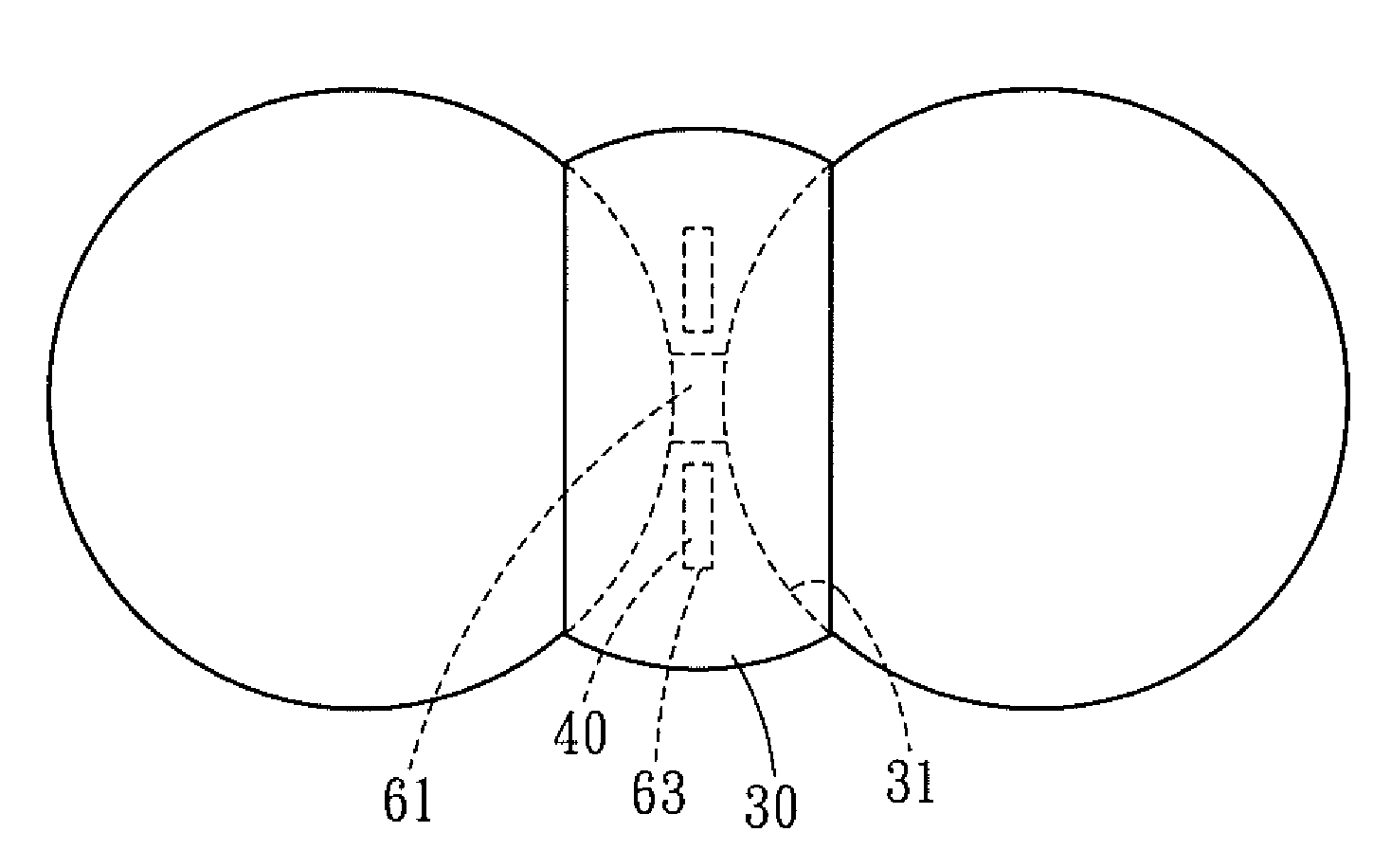
[0044]The respective spacers 30 are formed with arc grooves 31 and a through hole 61, and two circular receiving spaces 63 are defined beside the through hole 61 for accommodation of the magnetic filler 40. The arc grooves 31 can enable the magnetic filler 40 of the spacers 30 to be adsorbed on the balls 20 more stably and effectively, and the through hole 61 can reduce the friction between the spacer 30 and the balls 20 at both sides thereof.

[0045]Referring finally to FIGS. 11-13, which shows a forth embodiment of the present invention. Each of the spacers 30 is formed with a semicircular receiving space 62 located at a side of the center of the respective spacers 30 for accommodation of the magnetic filler 40, and the specific gravity of the magnetic filler 40 is different from that of the spacers 30.

[0046]The semicircular receiving space 62 can enable t...


PUM


Abstract

A spacer contains a magnetic filler and is disposed between the magnetic conductive balls. The magnetic filler produces an indirect magnetic attractive force on the balls, therefore, when the interval between the two neighboring balls is overlarge, the spacer will not tip over under the effect of gravity or centrifugal force, but will be adsorbed on the balls by the magnetic filler.

Description

BACKGROUND OF THE INVENTION[0001]1. Field of the Invention[0002]The present invention relates to a spacer that is used in a linear transmission element and operates between balls of the linear transmission element, this spacer will not tip over under the effect of gravity or centrifugal force, thus enabling the linear transmission element to operate more smoothly.[0003]2. Description of the Prior Art[0004]Since linear transmission products are being applied more and more widely in the modern industry, various linear transmission mechanisms have widely come into human life, manufacturing factory and high science and technology instruments, such as linear guideway, ball screw, and the like. Particularly in a large-scale precision mechanism are usually installed various large and small ball screws or linear guideway systems. Although the technology for linear transmission element is developing fast, consumers still need the technology to be improved uninterruptedly. Therefore, there ar...

Claims


Application Information

Patent Timeline
Patent Type & Authority Patents(United States)
IPC IPC(8): F16C33/37
CPCF16C29/0685F16C33/3706
Inventor CHEN, YAN-YULIN, KENNYWU, WEN-CHIA
Owner HIWIN TECH
Why Eureka
Try Eureka