Connector structure

a technology of connecting structure and connector, applied in the direction of coupling device connection, coupling device details, two-pole connection, etc., can solve the problems of ineffective and stably installation, and achieve the effect of convenient and stably installation of illumination elements

Inactive Publication Date: 2008-12-02
SINGATRON ELECTRONICS CHINA
View PDF2 Cites 4 Cited by
  • Summary
  • Abstract
  • Description
  • Claims
  • Application Information

AI Technical Summary

Benefits of technology

[0006]The primary object of present invention is to provide a connector structure, wherein a locking seat is moved transversally to be joined with a body, and is corresponding to an illumination element, so as to conveniently and stably install the illumination element without dropping out.

Problems solved by technology

However, to install the illumination element A5 and the locking seat A6 at a same time is indeed a very inconvenient method of assembly, and as the elements are easy to drop out, they cannot be effectively and stably installed.

Method used


Image

  • Connector structure
  • Connector structure
  • Connector structure

Examples


Embodiment Construction

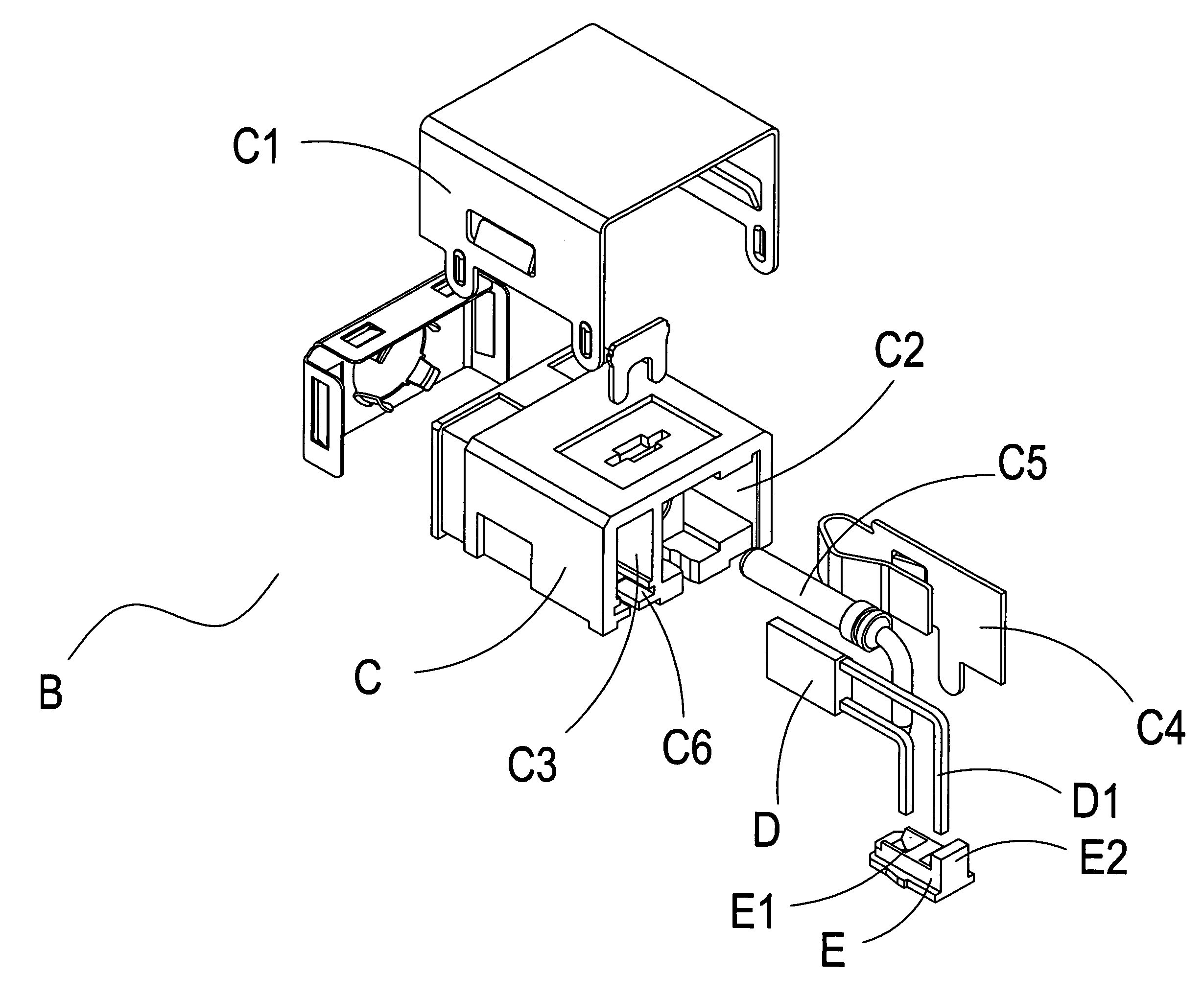
[0015]Referring to FIG. 3 and FIG. 4, a connector B of the present invention comprises a body C, an illumination element D, and a locking seat E, wherein the body C is extended with a cover C1, and an interior of the body C is transfixed with a first tunnel C2 and a second tunnel C3. An interior of the first tunnel C2 is provided with a conduction terminal C4 and a contact terminal C5, and an interior of the second tunnel C3 is provided with the illumination element D. In addition, a locking slot C6 of the second tunnel C3 is extended with the locking seat E which can be moved transversally. Pins D1 of the illumination element D are transfixed into through-holes E1 of the locking seat E, and the locking seat E is extended with a protruded member E2 to prevent from inserting by mistake. By installing the illumination element D onto the locking seat E, and by transversal movement of the locking seat E in the locking slot C6, the illumination element D can be assembled conveniently and...


PUM


Abstract

A connector structure is constituted by a body, an illumination element, and a locking seat, wherein the body is extended with a cover, and an interior of the body is provided with a first tunnel having a contact terminal and conduction terminal, as well as a second tunnel having the illumination element and the locking seat. By installing the illumination element on the locking seat, and by transversal movement of the locking seat in a locking slot of the body, the illumination element can be conveniently assembled with the body, and the locking seat can be stably connected with the body without easily dropping out.

Description

BACKGROUND OF THE INVENTION[0001](a) Field of the Invention[0002]The present invention relates to a connector structure, and more particularly to a connector structure which is provided with a locking seat that is moved transversally to be joined with a body.[0003](b) Description of the Prior Art[0004]Referring to FIG. 1 and FIG. 2, a connector A is provided with a body A1, an interior of which is transfixed with a tunnel A2 that is installed with a conduction terminal A3, a contact terminal A4, and an illumination element A5, and a lower part of which is extended with a locking seat A6 that is joined with the illumination element A5 and is locked at the body A1. When the illumination element A5 is to be disposed in the tunnel A2, the locking seat A6 should be installed on the body A1 simultaneously. However, to install the illumination element A5 and the locking seat A6 at a same time is indeed a very inconvenient method of assembly, and as the elements are easy to drop out, they c...

Claims


Application Information

Patent Timeline
Patent Type & Authority Patents(United States)
IPC IPC(8): H01R3/00
CPCH01R13/7175H01R24/38H01R2103/00
Inventor XIE, QUI-DA
Owner SINGATRON ELECTRONICS CHINA
Why Eureka
Try Eureka