
Dynamic splint assemblies

a splint and dynamic technology, applied in the field of orthopaedic devices, can solve the problems of hand not working properly, fingers not being able to grasp objects, and wrists or fingers not being able to extend to grasp objects

Active Publication Date: 2008-12-02
SAEBO
View PDF47 Cites 7 Cited by
  • Summary
  • Abstract
  • Description
  • Claims
  • Application Information

AI Technical Summary

Benefits of technology

The dynamic splint assembly effectively counters hypertonicity by providing a continuous restoring force to extend the fingers and thumb, enabling patients to achieve extended positions that would otherwise be impossible, aiding in rehabilitation and therapy by offering adjustable resistance and secure fitting.

Problems solved by technology

Many have some shoulder and elbow movements, but have a non-functioning hand and are unable to extend their wrist or fingers to grasp an object.

Method used


Image

  • Dynamic splint assemblies
  • Dynamic splint assemblies
  • Dynamic splint assemblies

Examples


Embodiment Construction

[0063]As a preliminary matter, it will readily be understood by one having ordinary skill in the relevant art (“Ordinary Artisan”) that the invention has broad utility and application. Furthermore, any embodiment discussed and identified as being “preferred” is considered to be part of a best mode contemplated for carrying out the invention. Other embodiments also may be discussed for additional illustrative purposes in providing a full and enabling disclosure of the invention. Moreover, many embodiments, such as adaptations, variations, modifications, and equivalent arrangements, will be implicitly disclosed by the embodiments described herein and fall within the scope of the invention.

[0064]Accordingly, while the invention is described herein in detail in relation to one or more embodiments, it is to be understood that this disclosure is illustrative and exemplary of the invention, and is made merely for the purposes of providing a full and enabling disclosure of the invention. Th...


PUM


Abstract

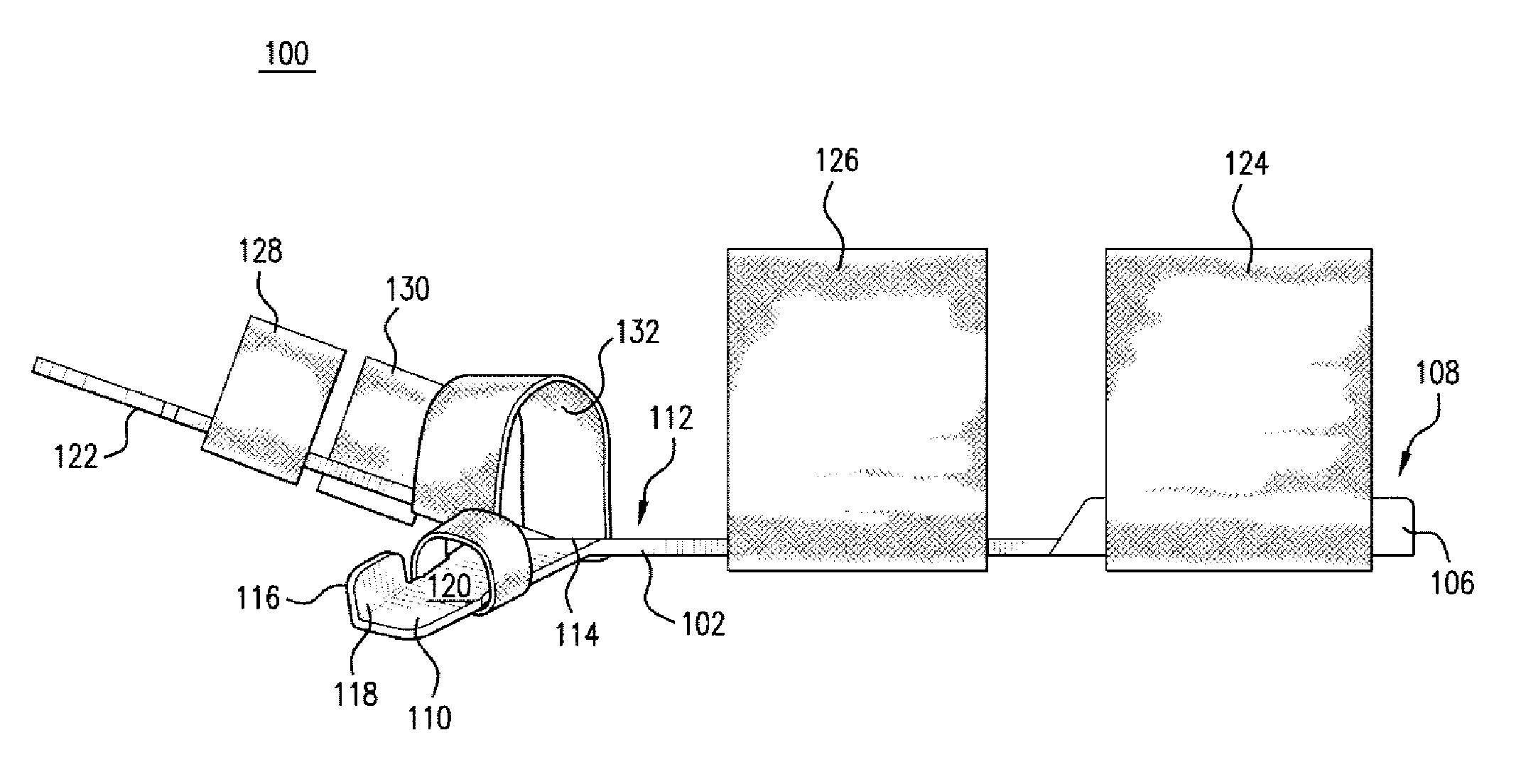
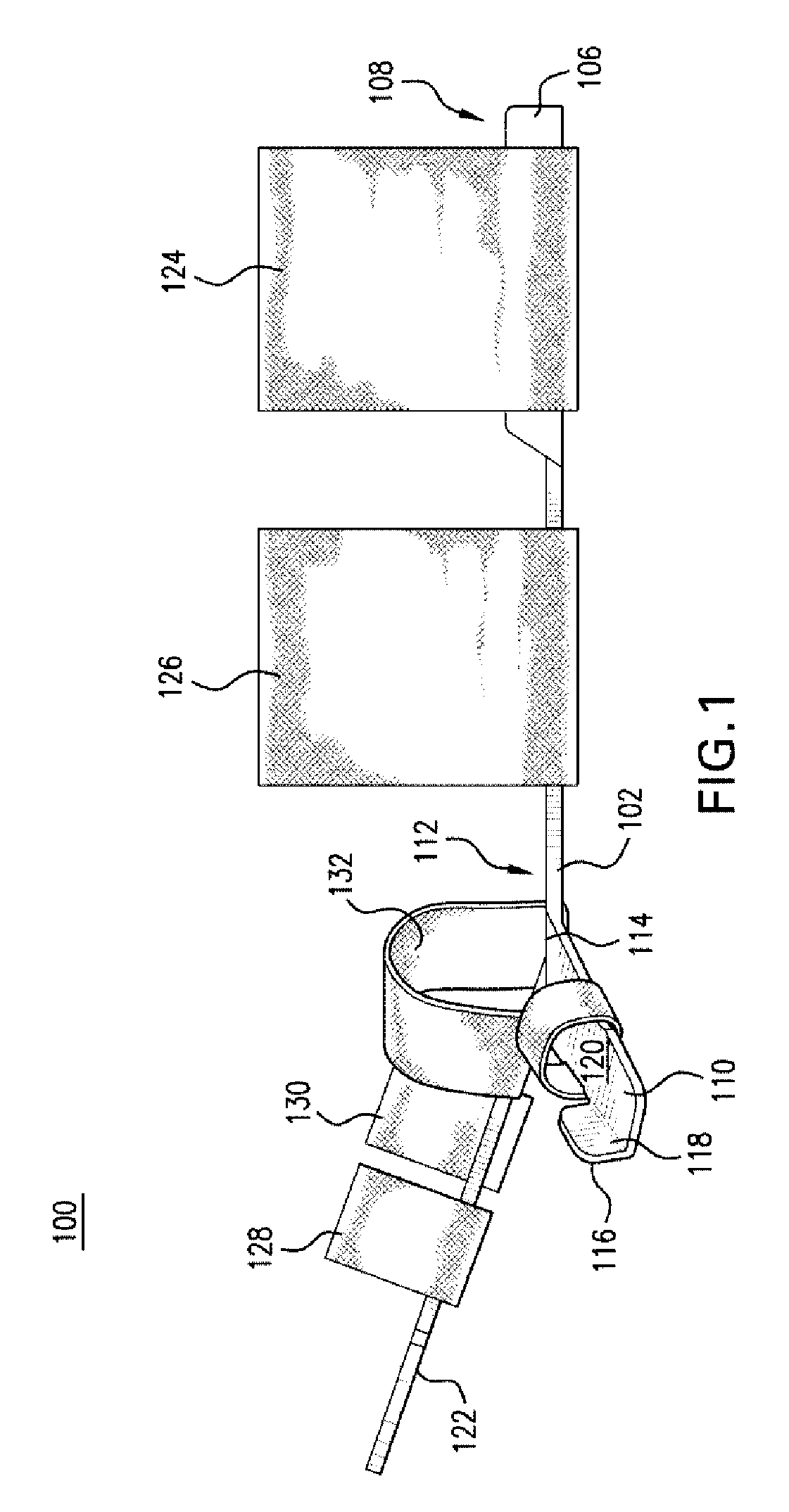
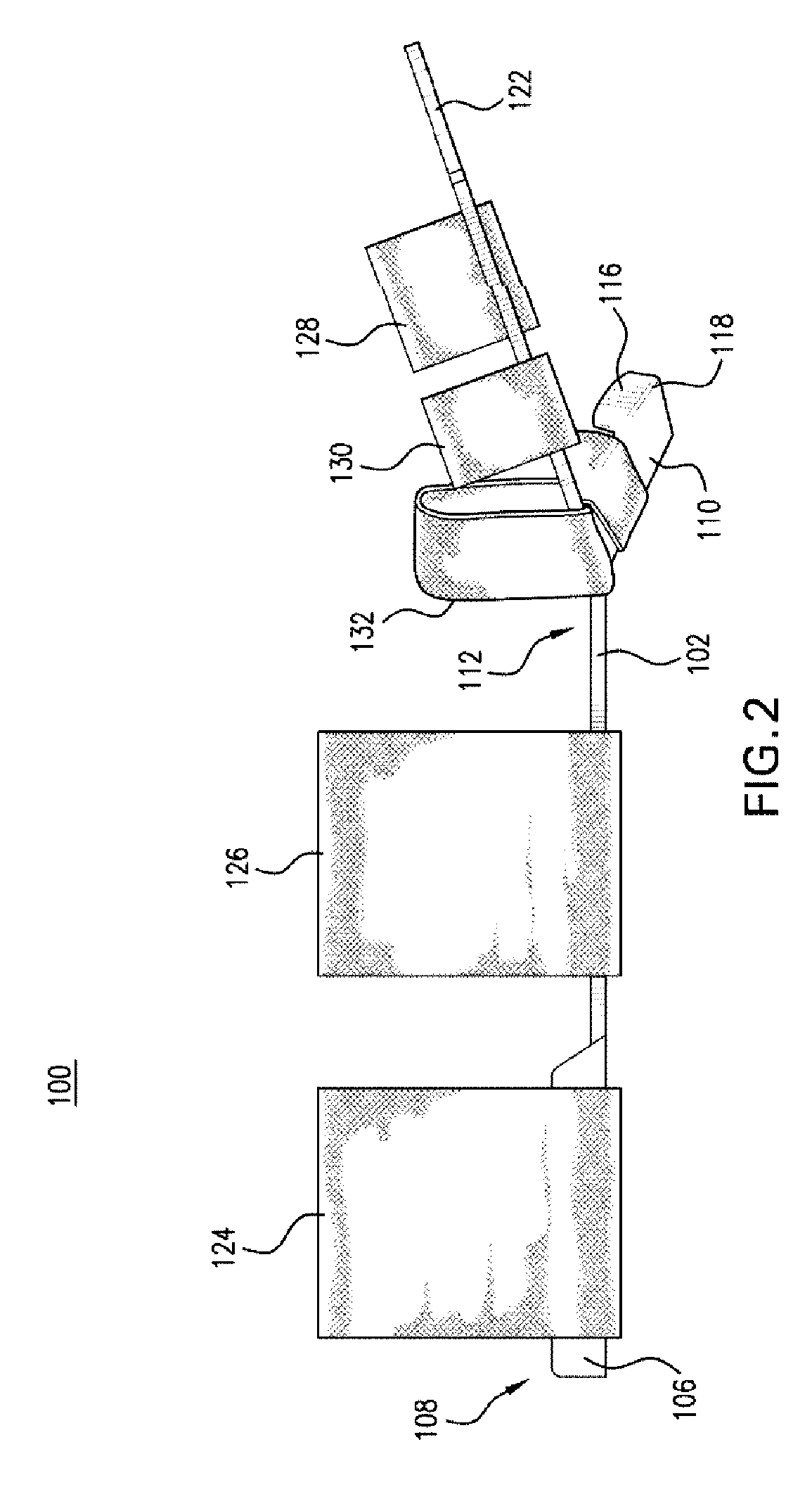
A dynamic splint assembly for a hand includes a forearm support section configured to abut the dorsal side of a forearm and span a wrist; and a hand support section connected to the forearm support section. The hand support section is configured to abut the dorsal side of the hand including the dorsal side of the length of a finger. The hand support section comprises a resilient material that, in response to bending, such as during flexion of the finger, generates a continuous restoring force in opposition to such bending, whereby the finger in flexion is urged toward extension. The forearm support section, in contrast, does not generate, in response to bending, a continuous restoring force in opposition to such bending, whereby a wrist may be selectively oriented in one of many fixed dispositions having varying degrees of flexion and extension relative to a forearm.

Description

CROSS-REFERENCE TO RELATED APPLICATIONS[0001]The present application for purposes of the United States is a nonprovisional patent application of, and claims priority under 35 U.S.C. § 119(e) to each of U.S. provisional patent application Ser. No. 60 / 640,370, filed on Dec. 30, 2004, and titled “Dynamic Splint Assembly,” which provisional patent application is incorporated by reference herein; and to U.S. provisional patent application Ser. No. 60 / 669,109, filed on Apr. 7, 2005, and titled “Dynamic Splint Assembly,” which provisional patent application is incorporated by reference herein.COPYRIGHT STATEMENT[0002]All of the material in this patent document is subject to copyright protection under the copyright laws of the United States and other countries. The copyright owner has no objection to the facsimile reproduction by anyone of the patent document or the patent disclosure, as it appears in official governmental records but, otherwise, all other copyright rights whatsoever are re...

Claims


Application Information

Patent Timeline
Patent Type & Authority Patents(United States)
IPC IPC(8): A61F5/00A61F13/00
CPCA61F5/05866
Inventor FARRELL, JOHN FLETCHERHOFFMAN, HENRY B.KOVACEVICH, IAN D.
Owner SAEBO
Learn More