Adjustment method, image reading device, and image forming apparatus for adjusting read sensors

a technology of image reading and read sensor, which is applied in the direction of electrical equipment, instruments, computing, etc., can solve the problems of increasing the cost of the image reading device, increasing the production cost, and increasing the complexity of the image data process

Active Publication Date: 2008-12-02
RICOH KK
View PDF13 Cites 16 Cited by
  • Summary
  • Abstract
  • Description
  • Claims
  • Application Information

AI Technical Summary

Benefits of technology

[0022]A more specific object of the present invention is to provide an adjustment methods, an image reading device, and an image forming apparatuses for adjusting read sensors, in which a displacement amount of an image can be easily measured at each joint of the plurality of reading sensors within a shorter time so as to suppress various discretions of operators with respect to a measurement result, the start pixel and the end pixel to read image data in the main scanning direction can be precisely determined and adjusted, and relative displacement amount of line images orthogonal to the sub-scanning direction can be precisely obtained, so as to properly combine partial images read by the plurality of reading sensors.
[0024]As described above, setting values concerning image data showing a parallel line pattern showing two parallel lines extending along the sub-scanning direction are stored in a recording unit of the image recording device beforehand. Alternatively, image data obtained by reading the sheet showing the parallel line pattern showing the two parallel lines extending along the sub-scanning direction. Either one of the image data is used to set a reference interval in the main scanning direction. The reference interval is compared with a line image interval in the main scanning direction between the two parallel line images obtained by reading the sheet so that each joint of the first read sensors and the second read sensors is placed between the two parallel straight lines. Therefore, the displacement amounts at joints the first read sensors and the second read sensors in an image can be easily measured within a shorter time. Moreover, the various discretions of operators can be suppressed with respect to the measurement result. Furthermore, the start pixel and the end pixel to read image data in the main scanning direction can be precisely determined and corrected.
[0026]As described above, setting values concerning image data showing a parallel line pattern showing two parallel lines extending along the sub-scanning direction are stored in a recording unit of the image recording device beforehand. Alternatively, image data obtained by reading the sheet showing the parallel line pattern showing the two parallel lines extending along the sub-scanning direction. Either one of the image data is used to set a reference interval in the main scanning direction. The reference interval is compared with an line image interval in the main scanning direction between the two parallel line images obtained by reading the sheet so that each joint of the first read sensors and the second read sensors is placed between the two parallel straight lines. Therefore, the displacement amounts at joints the first read sensors and the second read sensors in an image can be easily measured within a shorter time. Moreover, the various discretions of operators can be suppressed with respect to the measurement result. Furthermore, the start pixel and the end pixel to read image data in the main scanning direction can be precisely determined and corrected. In addition, relative displacement amounts of the straight line images orthogonal to the sub-scanning direction can be precisely obtained, so as to properly combine partial images to form a composite image.
[0028]As described above, at least one reading sensor may read the two parallel lines extending along the sub-scanning direction located in a range of the reading sensor at a place other than the joints, beforehand. Image data from the reading sensor may be maintained in the recording unit of the image reading device and the reference interval between the two parallel lines may be determined based on the image data. Even if the sheet as a reference is skewed or the sheet is extended or reduced due to a temperature and relative humidity, reference interval patterns in the main scanning direction can be prevented from an error.
[0030]As described above, in an available read range as one line combining read ranges of the plurality of reading parts, one range of one of the plurality of reading parts may be arbitrarily selected to fix the start pixel and the end pixel to read image data. For each of other reading parts, the start pixel and the end pixel, which are not fixed, may be determined and corrected. Each range of other reading parts can be maintained to be constant. As a result, it is possible to easily maintain the available read range as one line combining the read ranges of the plurality of reading parts in a shorter time.
[0032]In order to recognize a subject line to be evaluated, a “threshold search” using a pixel level and a “centroid search” using a centroid method may be used as two steps. A coordinate group recognized as straight lines is obtained by the “threshold search”, and a subject straight line to be evaluated is obtained by the “centroid search”. One straight line is formed by pixels of an x direction and a y direction. Since a read density difference occurs for each pixel unit, the x coordinate and the y coordinate of the straight line can be precisely obtained.

Problems solved by technology

As a result, a cost of the image reading device 10a is increased.
This is a problem of the first type.
As a result, an image data process becomes complicate more than the image data process in the first type.
However, the methods described in the above items (1) and (2) take time and workload to measure the displacement amount at the joints of the read sensors arranged at the upstream and the downstream, and increase a production cost.
Moreover, deviation of measurement results by various operators occurs, and a precise setting cannot be conducted.

Method used


Image

  • Adjustment method, image reading device, and image forming apparatus for adjusting read sensors
  • Adjustment method, image reading device, and image forming apparatus for adjusting read sensors
  • Adjustment method, image reading device, and image forming apparatus for adjusting read sensors

Examples


first embodiment

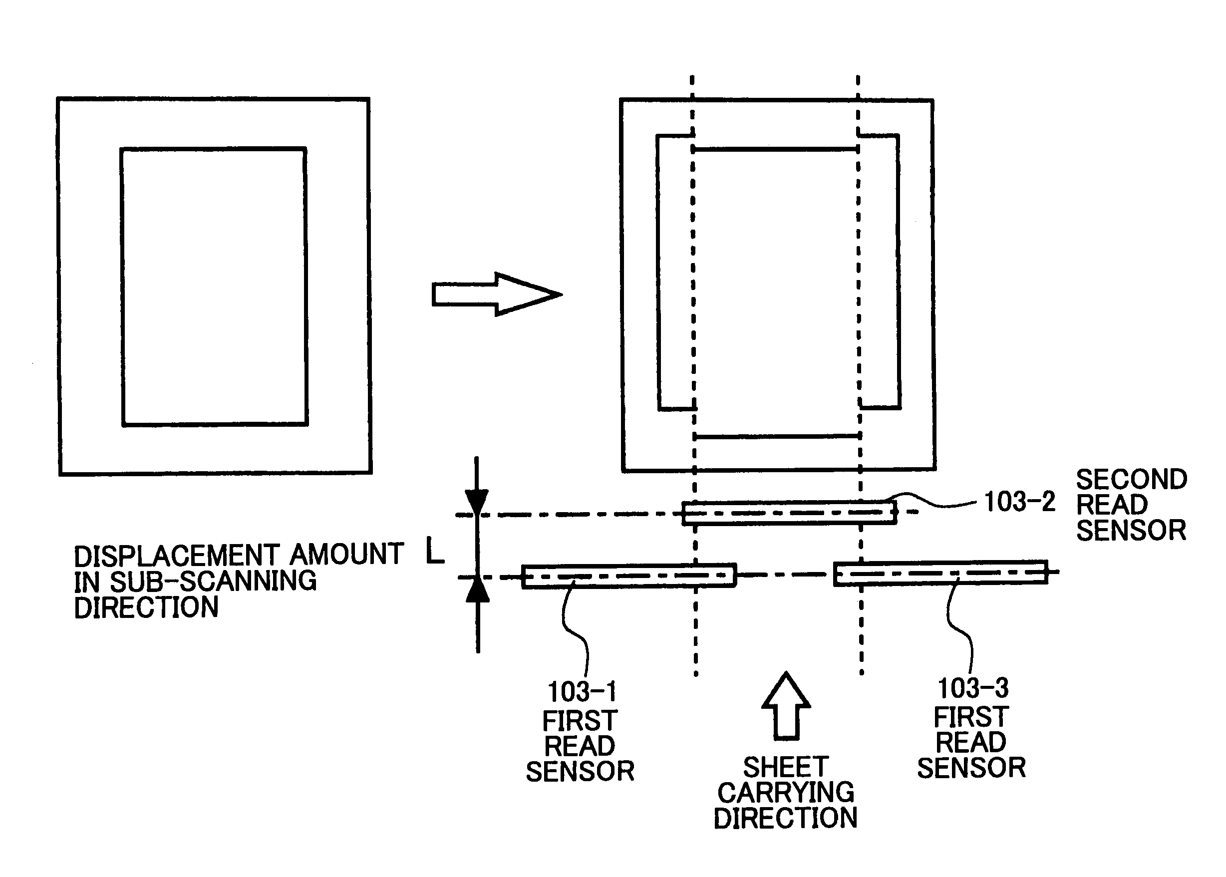
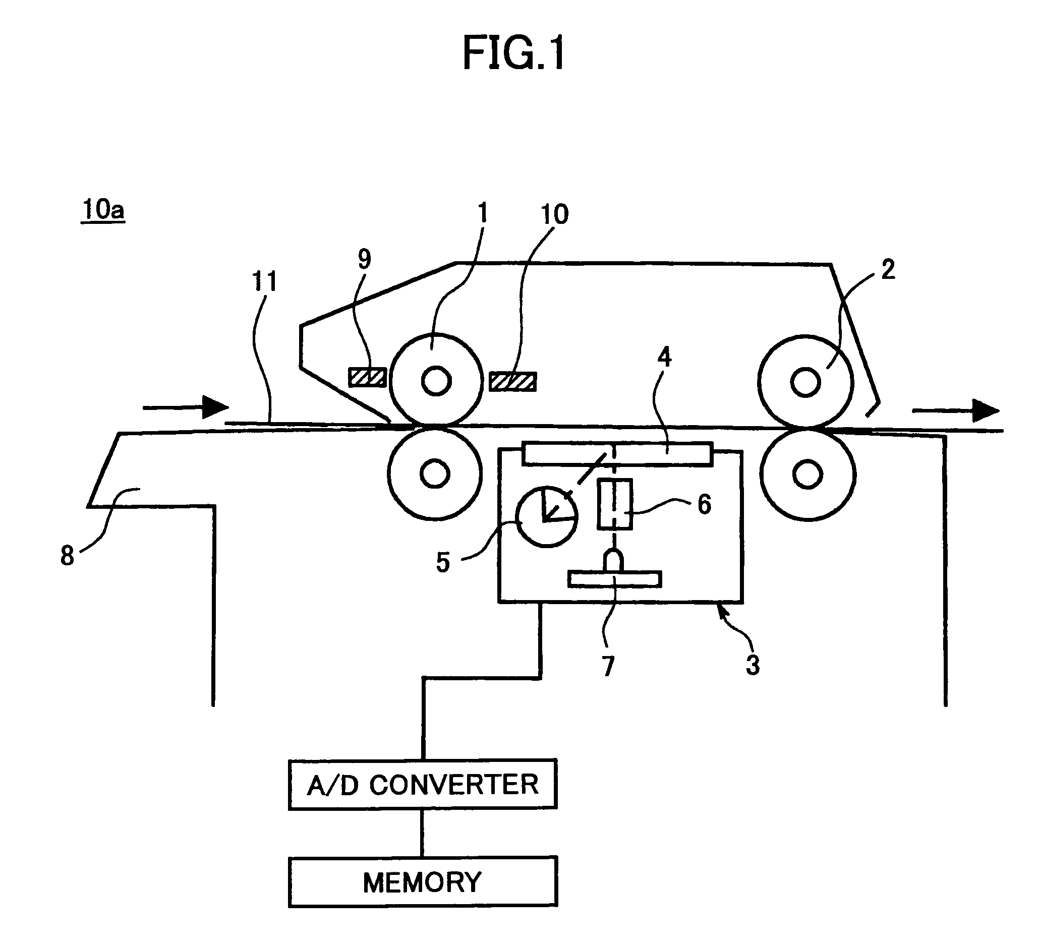
[0051]FIG. 4A is a schematic top plan view of an image reading device 50a according to an embodiment of the present invention, and FIG. 4B is a schematic side view of the image reading device 50a according to the embodiment of the present invention.

[0052]Referring to FIG. 4A and FIG. 4B, in the image reading device 50a, an image of a sheet 111, which is carried by first carriage rollers 101 to locate between a contact glass 104 and a pressing plate 113, is read by first read sensors 103-1 and 103-3 arranged at an upstream and a second read sensor 103-2 arranged at a downstream, and the sheet 111 is ejected by second carriage rollers 102. In FIG. 4A, a distance L is a distance in a sub-scanning direction at joints between the first read sensors 103-1 and 103-3 and the second read sensor 103-2, and the distance L corresponds to a displacement amount in the sub-scanning direction. A distance LL is a distance in the sub-scanning direction at joints between the second carriage rollers 10...


PUM


Abstract

The adjustment method is disclosed in that a predetermined reference interval in a main scanning direction is compared with each interval in the main scanning direction obtained by reading a sheet so that each joint of image is located between two parallel lines, a start pixel and an end pixel to read image data at each joint are determined and adjusted by calculating each interval difference, a reference straight line extending along the main scanning direction is compared with each of the plurality of straight line images extending along the main scanning direction at joints of images, and a delay time for reading sensors is adjusted by calculating an average value of relative displacement amounts.

Description

BACKGROUND OF THE INVENTION[0001]1. Field of the Invention[0002]The present invention generally relates to an image forming apparatus such as a copier, a facsimile, a printer, and a like for forming an image by using an electronic photograph method and an inkjet method, and more particularly to an adjustment method for adjusting a plurality of reading parts, an image reading device for adjusting a plurality of reading parts, and an image forming apparatus for adjusting a plurality of reading parts, in which higher image quality of an image can be realized in that no image displacement caused by duplicated pixels and dropped pixels occurs.[0003]2. Description of the Related Art[0004]In the following, one of technologies concerning an image reading device will be described with reference to FIG. 1 through FIG. 3. FIG. 1 is a schematic diagram showing a configuration of the image reading device. The image reading device 10a recognizes that a sheet 11 is inserted into the image reading ...

Claims


Application Information

Patent Timeline
Patent Type & Authority Patents(United States)
IPC IPC(8): H04N1/387H04N1/04H04N1/40
CPCH04N1/1903H04N1/193H04N1/1934H04N1/121
Inventor IWASAKI, TAKESHI
Owner RICOH KK
Why Eureka
Try Eureka