Stair rod bracket

a technology for stair rods and brackets, which is applied in the direction of carpet fasteners, multi-purpose tools, flooring fabrics, etc., can solve the problems of rod falling on people, pets or objects, special problems of using stair rods, etc., and achieves the effect of convenient assembly and disassembly

Inactive Publication Date: 2008-12-09
STAIR HOLD
View PDF41 Cites 10 Cited by
  • Summary
  • Abstract
  • Description
  • Claims
  • Application Information

AI Technical Summary

Benefits of technology

[0013]The present invention provides a stair rod bracket and a stair rod set. The stair rod bracket is slidably interconnected for easy assembly and disassembly. The stair rod set includes a pair of slidable interconnecting stair rod brackets, a stair carpet retaining rod and a pair of finials. The stair rod set is advantageously useful for releasably fastening a carpet runner to a staircase. The invention also provides a stair rod bracket kit and a stair rod set kit having the slidable interconnecting stair rod brackets.

Problems solved by technology

The use of a “stair eye” type bracket poses special problems.
This poses a particular danger in certain types of staircases, which are designed as open staircases on one, or both sides.
Slippage of the rod could result in the rod falling on persons, pets or objects under and adjacent the open side(s) of the staircase.
Use of the stair bracket having an end wall, however, introduces problems associated with ease in opening and closing the brackets for removal of the stair rod in order to remove the carpet for cleaning, and for cleaning and polishing the stair rod, brackets and finials.
Special problems related to easily removing the stair rod from the bracket are associated with both the end wall type bracket and with the open eye-type bracket.
The use of brackets having hingeably upliftable, pivotally slidable or moveably upliftable top portions have required the use of fasteners or projections which make the bracket harder to use and more expensive to fabricate.
Also the upliftable, pivoting or moveable portions may be subject to breaking off or loosening after extended use.
In addition, cleaning and polishing these types of brackets is more difficult because they have more parts and recesses that require cleaning.
Further, the messy job of cleaning and polishing the top portion of the bracket frequently must be done on the staircase, unless both the top portion and the bottom portion of the bracket are removed.
Another problem with stair eye brackets which are traversely engageable is that accidentally jarring the top portion of the bracket can cause transverse overtravel, e.g., the top portion of the bracket disengages from the bottom portion of the bracket, thus bending the bracket portions and / or the stair rod, or causing the stair rod to fall out of the bracket.
However, the use of springs and plungers adds to the complexity of using the bracket and the costs of making the bracket.
This, however, provides that the two portions of the bracket can only be connected by the sliding of one piece into the other in one direction.
This can be a problem when the brackets are connected in a tight corner, where limiting the connection of the two portions of the bracket in only one direction can make installation difficult.
Yet another problem with traversely engageable stair rod brackets, is that they often are connected together with dove-tail connections.
Such sharp edge connections are easily dented.
This leads to difficulty in slidably connecting the two members together to form the stair rod bracket, as the dove-tail projection cannot fit together correctly.
Still a further problem occurs when a person accidentally steps on the rod.
The application of pressure to the rod frequently causing bowing of the rod.
This, of course, may pose a safety problem, since, in addition, to the possibility of the lateral slippage, there is the possibility that the person may slip on the rod while walking up the steps.
Yet another problem exists when it is desired to change the decorative look of the stair rod set.
This can be expensive and time consuming.
A further problem with two-piece stair rod brackets, is that the interlocking design of the brackets can only be accomplished by casting the metal for each piece in separate molds.
This can often lead to problems with the two pieces fitting together snugly to provide a tight fitting stair rod bracket, as variations in the separate molds often arise.

Method used


Image

  • Stair rod bracket
  • Stair rod bracket
  • Stair rod bracket

Examples


Embodiment Construction

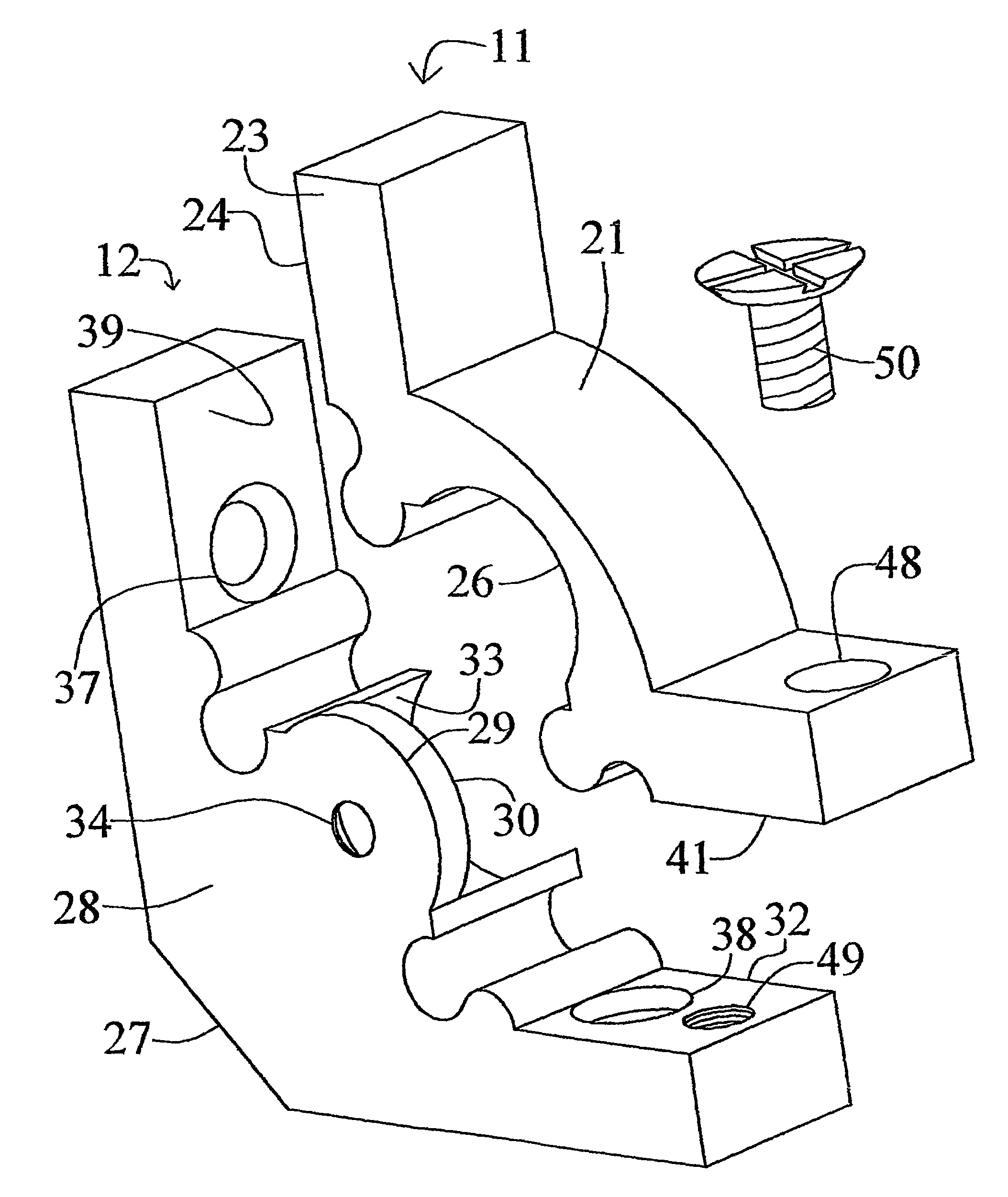
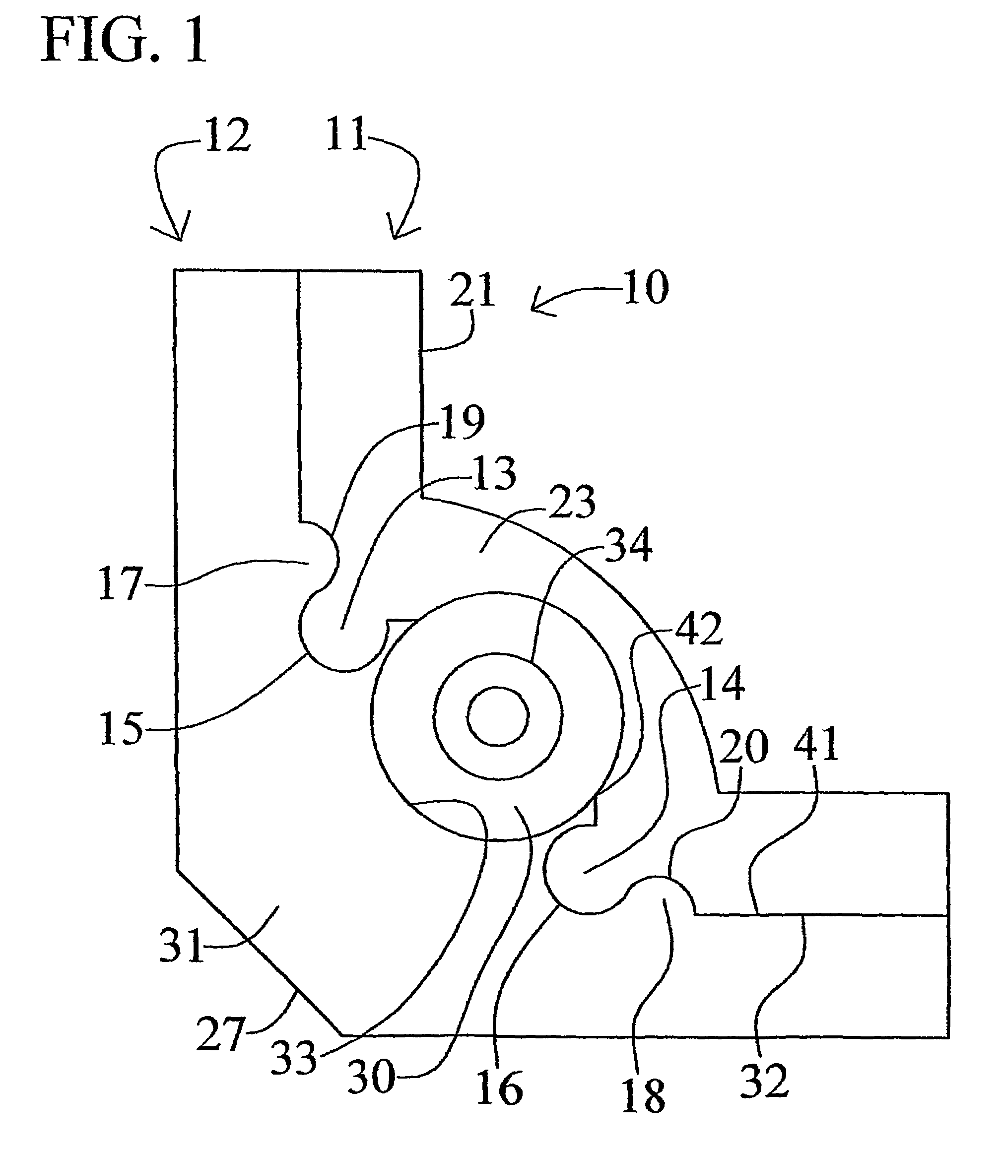
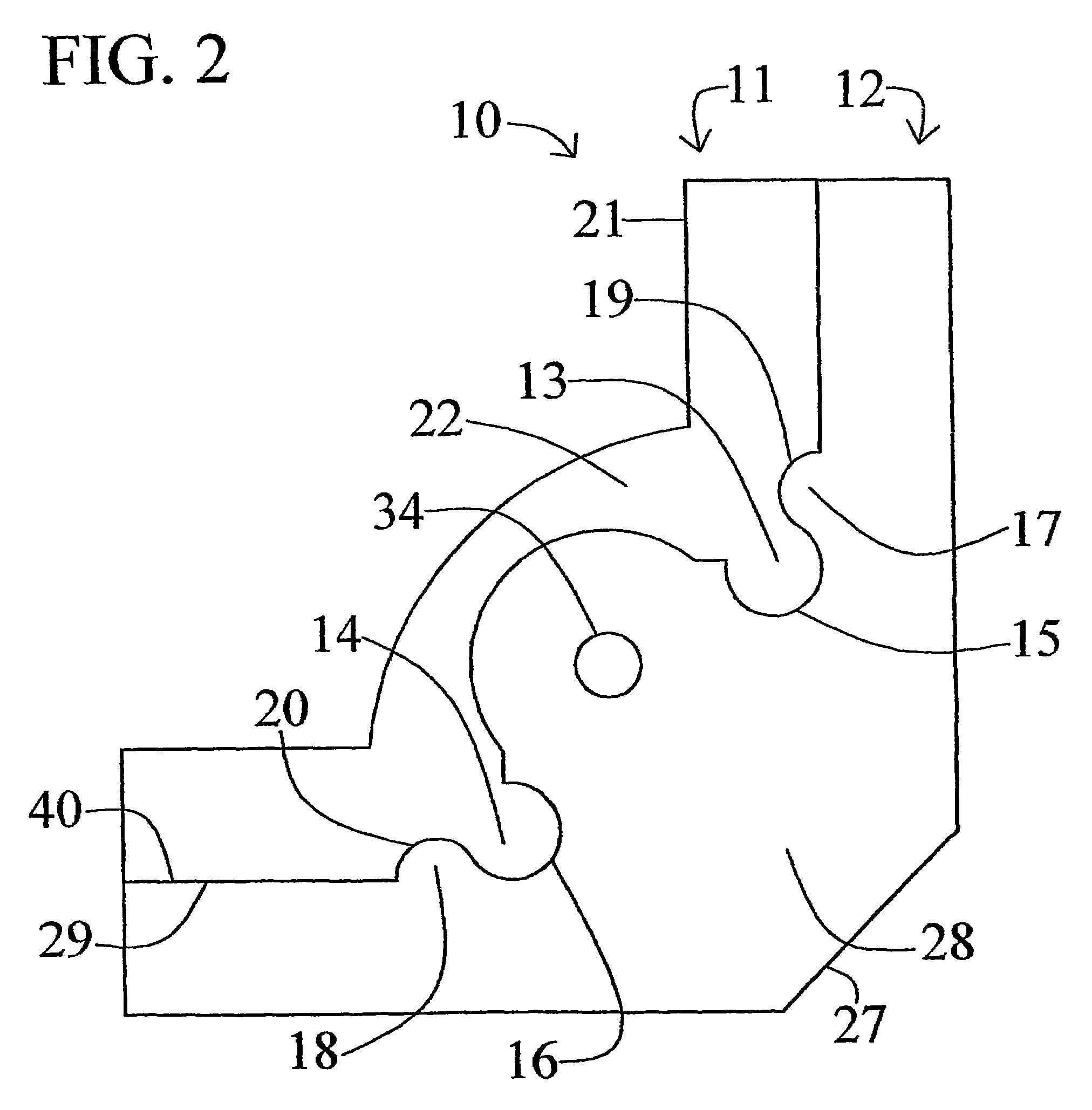
[0027]The present invention relates broadly to a stair rod bracket. Specifically, the invention provides a stair rod bracket and a stair rod set having a pair of slidably interconnecting stair rod brackets, a stair carpet retaining rod and a pair of finials. Accordingly, the present invention will now be described in detail with respect to such endeavors; however, those skilled in the art will appreciate that such a description of the invention is meant to be exemplary only and should not be viewed as limitative on the full scope thereof.

[0028]The stair rod brackets of the present invention are best shown in FIGS. 1-4. A bracket generally designated as reference numeral 10 of the present invention includes a top portion 11 and a bottom portion 12. The top portion 11 and the bottom portion 12 of each bracket 10 slidably engage each other, i.e. they interconnect permitting transverse (lateral) engagement of the top portion 11 with the bottom portion 12. Each bracket 10 has a plurality...


PUM


Abstract

The present invention provides a transversely interconnecting slidable stair rod bracket. The bracket may also be provided for use in a stair rod set, the set also including a stair carpet retaining rod and a finial. The bracket has a top portion and a bottom portion. The top portion having a plurality of projections and complementary shaped channels for receiving projections from the bottom portion; the bottom portion contains a rod-receiving portion, an outside end wall with an aperture therein for accepting either a threaded finial fastener which engages with a “female” finial, or the fastening portion of a “male” finial, and a plurality of projections and complementary shaped channels for receiving projections from the top portion.

Description

CROSS-REFERENCE TO RELATED APPLICATIONS[0001]This application claims the benefit of priority from U.S. application Ser. No. 10 / 486,296 filed Feb. 9, 2004, which is a national stage filing under 35 U.S.C. 371 of International Application No. PCT / US02 / 25293 filed Aug. 9, 2002, which claims priority from U.S. Provisional Application. No. 60 / 311,192 filed Aug. 9, 2001, incorporated herein by reference.STATEMENT REGARDING FEDERALLY SPONSORED RESEARCH OR DEVELOPMENT[0002]Not applicable.[0003]This invention relates generally to stair rod brackets and to stair rod sets. In particular the invention relates to slidably interconnecting stair rod brackets and stair rod sets having a pair of slidably interconnecting stair rod brackets, a stair carpet retaining rod and a pair of finials. The invention also includes stair rod bracket kits and stair rod kits using the interconnecting stair rod bracket. The stair rod set is especially useful for releasable fastening carpet runners to a staircase.[00...

Claims


Application Information

Patent Timeline
Patent Type & Authority Patents(United States)
IPC IPC(8): A47G27/04A47G27/06
CPCA47G27/065Y10T16/124Y10T16/125Y10T16/122
Inventor ZOROUFY, ABOOLHASSAN
Owner STAIR HOLD
Why Eureka
Try Eureka