
Particle/cell separation device and compositions

a technology of particle/cell separation and composition, which is applied in the direction of tissue culture, diaphragm, biomass after-treatment, etc., can solve the problems of further damage, adverse effects of neutrophils in blood transfusions, and adverse effects of neutrophils, so as to prolong the storage time of unactivated platelets, and cause severe pain

Active Publication Date: 2008-12-09
BLUE ENGINE BIOLOGICS LLC
View PDF72 Cites 12 Cited by
  • Summary
  • Abstract
  • Description
  • Claims
  • Application Information

AI Technical Summary

Benefits of technology

The device effectively reduces neutrophil content by 10% or more in both small and large volumes of blood, mimicking the body's filtration process and reducing the risk of tissue inflammation and surgical complications.

Problems solved by technology

It has been established, however, that some of the cells in platelet rich plasma may adversely affect healing or even cause further damage (Iba et al Circulation October 2002).
Importantly, neutrophils are also considered to be harmful in blood transfusions.
Presently, however, these filters only work incompletely and are not functional for small volumes of blood.
Clearly, this filter would not be helpful for specifically reducing neutrophils in platelet rich plasma.
Also, no available device mimics the body's own ability to filter neutrophils.

Method used


Image

  • Particle/cell separation device and compositions
  • Particle/cell separation device and compositions
  • Particle/cell separation device and compositions

Examples


example 1

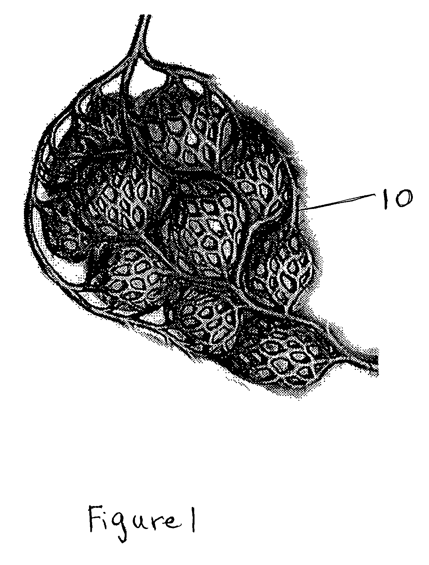
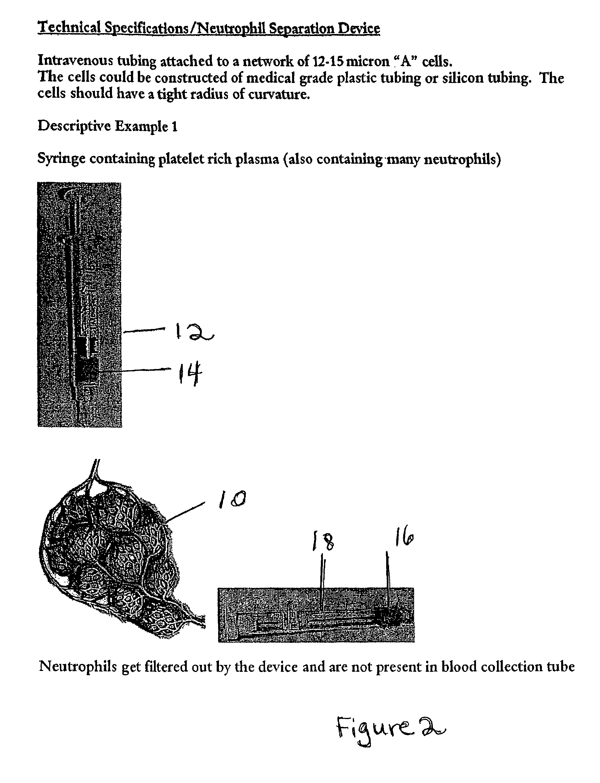
[0069]FIG. 5 shows a series of coiled tubes 30 for separation of the cellular components as described above. The tubes empty into a collection chamber 32. The sample to be purified enters through tubing 34 which may connect to the separation device 36 by a tubing adaptor 38. When a sample of platelet rich plasma enters the device, the smaller platelets are able to travel through the coiled tubing 30 to the collection chamber 32 more quickly than the neutrophils because of their smaller size and greater deformability. The neutrophils are retained in the coiled tubing.

example 2

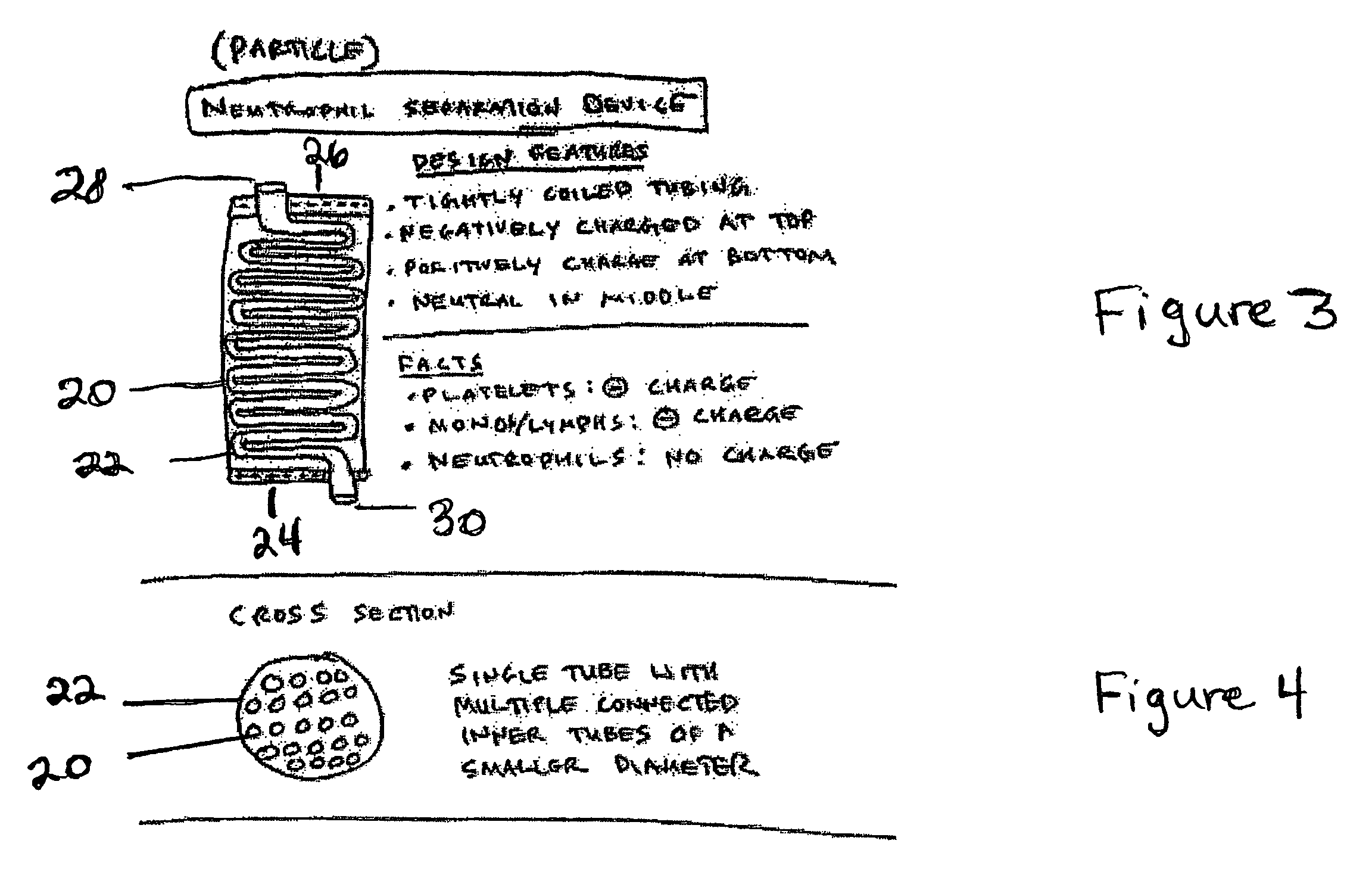
[0070]In an alternative design, the device could exist within an electrical field as shown in FIG. 6. For example, each of the coiled tubes shown in Example 1 above, could be encased within a chamber 40 that has a negative charge at its apex 42 and a positive charge at it base 44. The center of the chamber would be neutral in charge. When the sample enters the chamber, the platelets are able to travel through the coiled tubing as in Example 1 because of their small size and deformability. Additionally, as the platelets carry a net negative charge, their separation is further facilitated because of the positive charge at the bottom of the chamber.

example 3

[0071]In another alternative design, the device could be made of tubing that conducts electricity (FIG. 7). A charge 46 could then be run through the tubing and a gradient could be established. In the device shown in FIG. 7, the negatively charged blood components such as the platelets would be hindered by the positive charge of the walls of the tubing. In this example, the neutrophils would be collected first and separated from the other blood components. As in Example 2 above, the separation of the neutrophils from the platelets is based upon the small size, deformability and negative charge of the platelets relative to the neutrophils.


PUM

PropertyMeasurementUnit
diameteraaaaaaaaaa
volumeaaaaaaaaaa
diameteraaaaaaaaaa

Abstract

A particle / cell separation device is described which is particularly adapted for neutrophil depletion from a preparation of whole blood or platelet-rich plasma. Also described are blood and platelet rich plasma compositions produced using the device which are neutrophil-depleted.

Description

RELATED APPLICATIONS[0001]This application claim priority to U.S. Application No. 60 / 603,249 filed Aug. 20, 2004 which is incorporated herein by reference.BACK GROUND OF THE INVENTION[0002]1. Field of the Invention[0003]In one embodiment, the invention relates to a particle or cell separation device that separates specific cell types such as neutrophils or stem cells or particles from bodily fluids such as platelets and other blood products such as red cells and plasma. Also encompassed are the bodily fluids which have been processed through the disclosed device, particularly compositions which are enriched in platelets and depleted in neutrophils.[0004]2. Description of the Related Art[0005]Several devices are now on the market that can process a small amount of peripheral blood (20-60 cc) automatically or semiautomatically into a fraction of that plasma that is rich in platelets. The material obtained from these devices is known as platelet rich plasma or platelet concentrate. Thi...

Claims


Application Information

Patent Timeline
Patent Type & Authority Patents(United States)
IPC IPC(8): C02F1/40
CPCC12N5/0087A61K35/16
Inventor MISHRA, ALLAN
Owner BLUE ENGINE BIOLOGICS LLC
Learn More