Constant magnification imaging method and system

a constant magnification and imaging system technology, applied in the field of high resolution amplitude data collection, can solve the problems of undistorted rectangular images, complicated further, and current methods for producing constant magnification images are either large and unwieldy

Active Publication Date: 2008-12-09
LOCKHEED MARTIN CORP
View PDF6 Cites 22 Cited by
  • Summary
  • Abstract
  • Description
  • Claims
  • Application Information

AI Technical Summary

Benefits of technology

[0005]The problems set forth above as well as further and other problems are solved by the present invention. The solutions and advantages of the present invention are achieved by the illustrative embodiment of the present invention described hereinbelow.

Problems solved by technology

This causes complications with contextual analysis software that is trying to determine if a particular block of text is a destination address, using relative position as one of the deciding factors.
The problem is complicated further if the parcels are not aligned on the conveyor belt as they pass the scan line and four out of the six sides are in various degrees of distortion.
These techniques remove the optical perspective property and images of leading and trailing sides of a box appear as if they were perfectly aligned side surfaces, resulting in undistorted rectangular images.
However, the current methods for producing constant magnification images are either large and unwieldy, such as telecentric optics, or are made up of high speed mechanisms, such as dynamic zoom / focus lens, that are prone to failure.
These devices also add significant cost to the camera system.

Method used


Image

  • Constant magnification imaging method and system
  • Constant magnification imaging method and system
  • Constant magnification imaging method and system

Examples


Embodiment Construction

[0022]The present invention is now described more fully hereinafter with reference to the accompanying drawings, in which the illustrative embodiment of the present invention is shown.

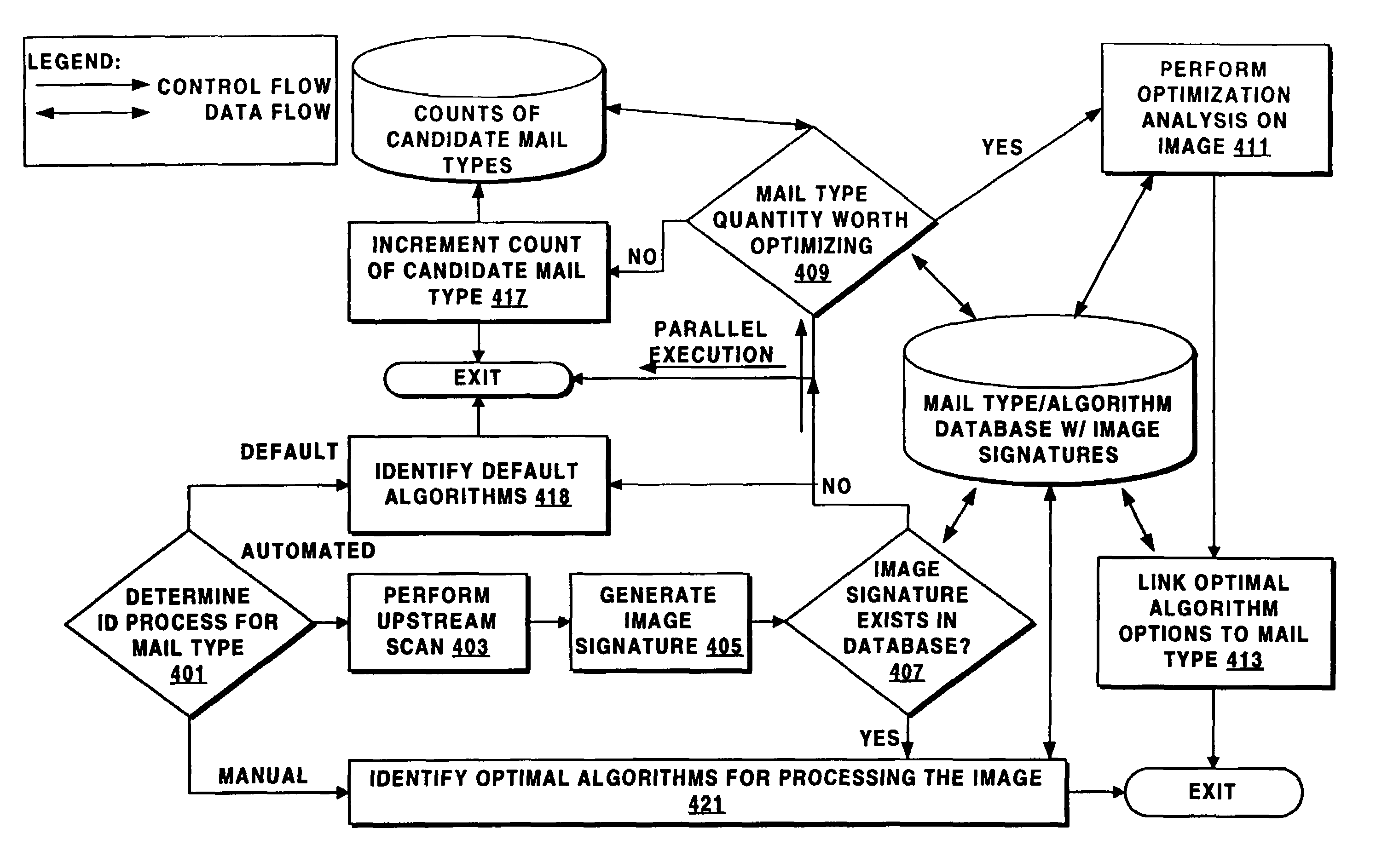
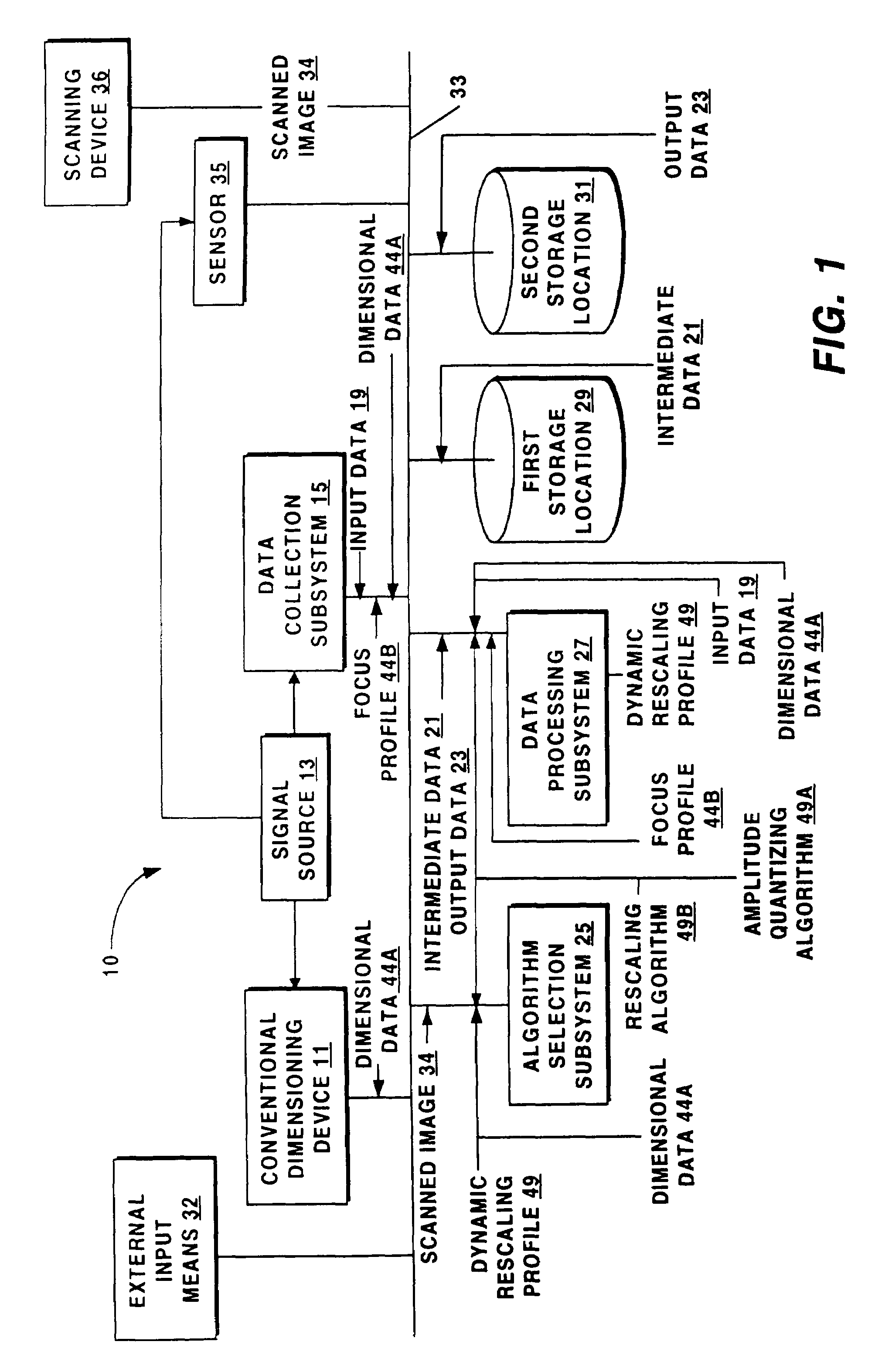
[0023]The components of system 10 of the present invention are schematically shown in FIG. 1. A schematic, illustrative embodiment of the present invention is also presented in the description accompanying FIG. 3. A practical application of the present invention is shown in FIG. 4. Referring now primarily to FIG. 1, system 10 generally includes a signal source 13, a data collection subsystem 15, an algorithm selection subsystem 25, a data processing subsystem 27, a scanning device 36, and an external input means 32. Scanning device 36 scans an object (such as parcel 61, FIG. 4) and sends scanned image 34 to algorithm selection subsystem 25 for classification of the object. The algorithm selection subsystem 25 classifies the image (see FIG. 5) and sends the appropriate rescaling algorithm 49B and amplit...


PUM


Abstract

A system and method for achieving constant magnification of a scanned three-dimensional item without the use of special optics or other specialized hardware. The system includes the dynamic computation of a camera parameter-dependent factor and applying that factor in real-time to the sampled signal resulting from the scan of the item.

Description

CROSS REFERENCE TO RELATED APPLICATIONS[0001]The present application is a continuation-in-part of U.S. patent application Ser. No. 10 / 361,350, entitled SYSTEM AND METHOD FOR INCREASING TEMPORAL AND SPATIAL CAPACITY OF SYSTEMS THAT AMPLITUDE QUANTIZE DATA PRIOR TO PROCESSING filed on Feb. 10, 2003 now U.S. Pat. No. 7,162,098, which claims priority to U.S. Provisional Application No. 60 / 412,650 filed Sep. 20, 2002, entitled SYSTEM AND METHOD FOR INCREASING TEMPORAL AND SPATIAL CAPACITY OF SYSTEMS THAT AMPLITUDE QUANTIZE DATA PRIOR TO PROCESSING which is incorporated herein in its entirety by reference. The present application claims priority to U.S. Provisional Application No. 60 / 432,768 filed on Dec. 12, 2002, entitled FIRMWARE SOLUTION FOR CONSTANT MAGNIFICATION IMAGING which is incorporated herein in its entirety by reference.BACKGROUND OF THE INVENTION[0002]This invention relates generally to high resolution amplitude data collection, and in particular, to a constant magnification...

Claims


Application Information

Patent Timeline
Patent Type & Authority Patents(United States)
IPC IPC(8): G06K9/36G06K9/32G06K9/34G06V30/10G06V30/162G06V30/166
CPCG06K9/38G06K9/42G06T3/40G06V30/10G06V30/424G06V30/162G06V30/166
Inventor DUGAN, PETER J.OUELLETTE, PATRICKPRATT, STEVEN J.RIESS, MICHAEL J.RUNDLE, ALFRED T.
Owner LOCKHEED MARTIN CORP
Why Eureka
Try Eureka