Extended depth of field imaging system using chromatic aberration

a chromatic aberration and depth of field technology, applied in the field of optical imaging systems, can solve problems such as blurred images, and achieve the effect of small chromatic aberration levels

Active Publication Date: 2007-05-29
PSC SCANNING INC
View PDF25 Cites 137 Cited by
  • Summary
  • Abstract
  • Description
  • Claims
  • Application Information

AI Technical Summary

Benefits of technology

[0011]In accordance with one aspect of the invention, a lens is formed of a highly dispersive material, such that the focal length changes significantly as a function of wavelength of incident light. A shorter wavelength is used to create a near field focus that lowers the optical magnification of the system, allowing the imager's resolution to be sufficient to read high density barcodes. An infrared light source can be used in some embodiments to enable high intensity illumination without disturbing the user. A second, shorter wavelength, for example visible light, can be used for high density reading as well as reading data sources such as barcodes that have little infrared contrast. In another embodiment, a doublet lens is arranged to provide a significant shift in focus as a function of wavelength. The doublet has a concave lens of crown glass in front of a convex lens of flint glass. This achieves substantial chromatic aberration to shift the focal length with wavelength.

Problems solved by technology

If a lens that was not color corrected was used in a white light illumination application, a very blurry image would result, as some colors of the illumination would provide in-focus images, while others would be out of focus, due to the chromatic aberration of the lens.
This is a reasonable limitation, for example, in many machine vision applications that look at the reflectivity profile of objects, such as optical character recognition, barcode reading, and inspection tasks.

Method used


Image

  • Extended depth of field imaging system using chromatic aberration
  • Extended depth of field imaging system using chromatic aberration
  • Extended depth of field imaging system using chromatic aberration

Examples


Embodiment Construction

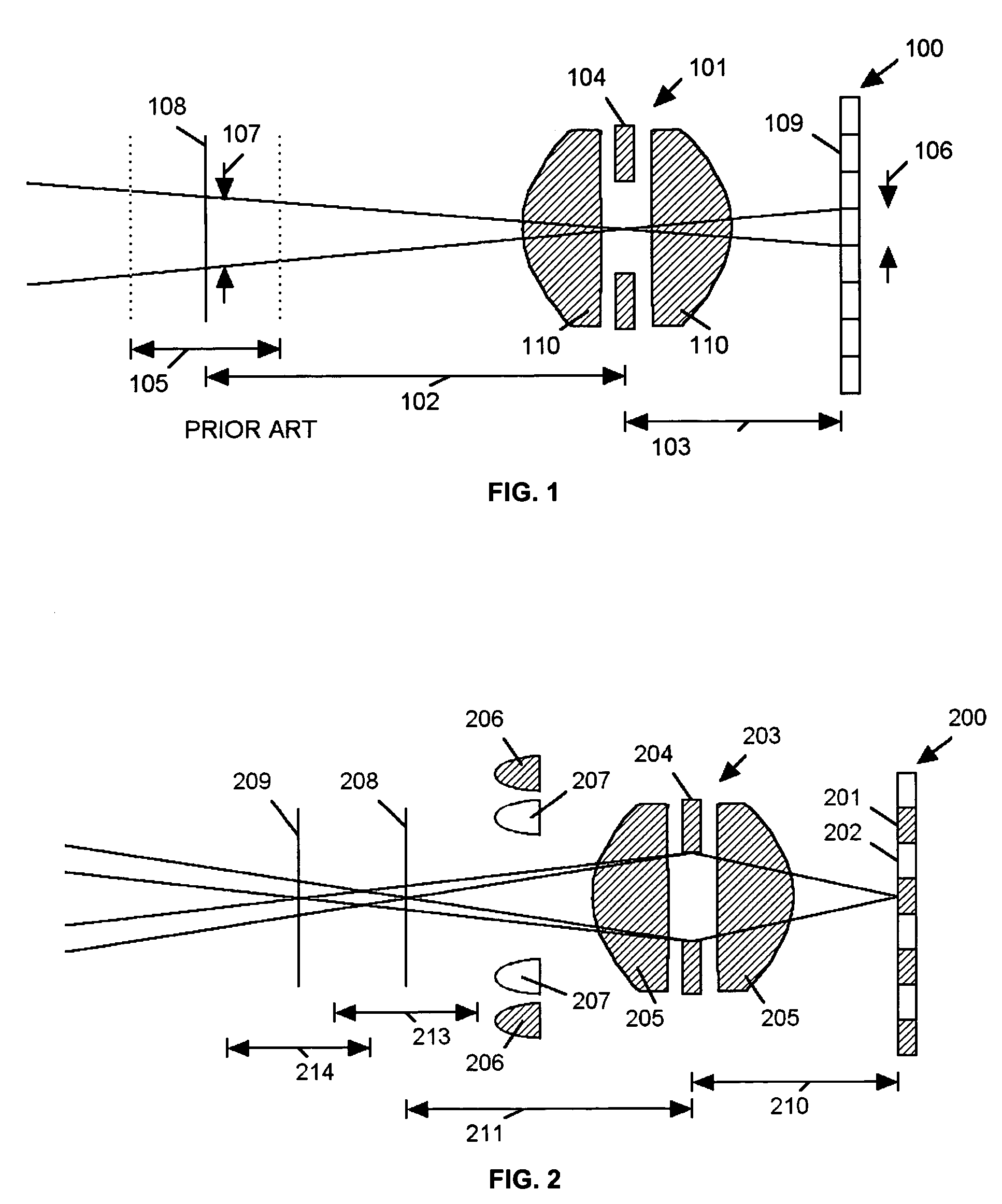
[0030]Referring to FIG. 1, an imaging system typical of the prior art consists of an imager 100 composed of a plurality of pixels 109 and a lens assembly 101 composed of one or more lenses 110 and an aperture 104 spaced from the imager 100 by a distance 103. The lens assembly provides a focused image of a target 108 onto the imager 100 when the target 108 is at distance 102 from the aperture 104. The lens assembly 101 provides a sufficiently focused image of target 108 over a depth of field 105 determined by the size of the aperture 104. The pixel size 106 of pixels 109 of imager 100 provides a projected resolution 107 based on the optical magnification, which is defined as the ratio of object distance 102 to image distance 103. So the resolution of an imaging system is determined by the pixel size 106 and the optical magnification. The depth of field is determined by the aperture size 104.

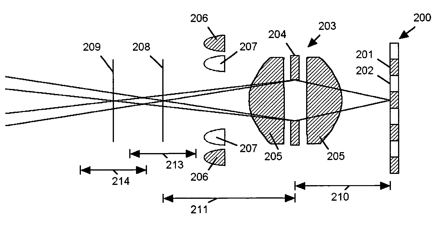
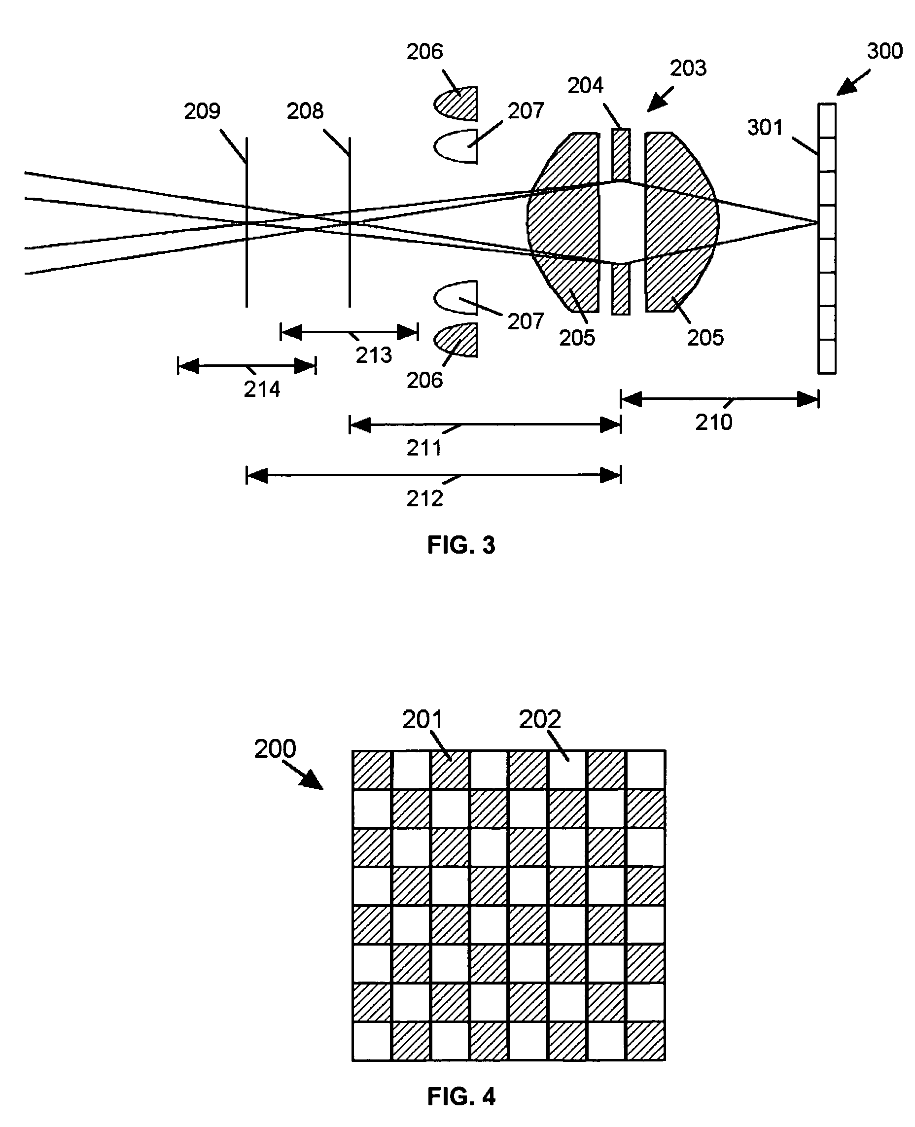
[0031]Referring to FIGS. 2 and 4, a color imager 200, composed of pixels 201 sensitive to one ...


PUM


Abstract

An imaging system (FIG. 3) is disclosed that has a wavelength dependent focal shift caused by longitudinal chromatic aberration in a lens assembly (203) that provides extended depth of field imaging due to focal shift (213,214) and increased resolution due to reduced lens system magnification. In use, multiple wavelengths of quasi-monochromatic illumination, from different wavelength LEDs (206,207) or the like, illuminate the target, either sequentially, or in parallel in conjunction with an imager (200) with wavelength selective (colored) filters. Images are captured with different wavelengths of illumination that have different focus positions (208,209), either sequentially or by processing the color planes of a color imager separately. Extended depth of field, plus high resolution are achieved. Additionally, information about the range to the target can be determined by analyzing the degree of focus of the various colored images.

Description

RELATED APPLICATION[0001]This application is related to U.S. application Ser. No. 11 / 045,213, filed Jan. 27, 2005, entitled IMAGING SYSTEM WITH A LENS HAVING INCREASED LIGHT COLLECTION EFFICIENCY AND A DEBLURRING EQUALIZER, by inventors Bryan L. Olmstead and Alan Shearin, incorporated herein by this reference. This application is also related to U.S. application Ser. No. 11 / 045,817, filed Jan. 28, 2005, entitled ILLUMINATION PULSING METHOD FOR A DATA READER, by inventor Bryan L. Olmstead, incorporated herein by this reference.COPYRIGHT NOTICE[0002]© 2005 PSC INC. A portion of the disclosure of this patent document contains material that is subject to copyright protection. The copyright owner has no objection to the facsimile reproduction by anyone of the patent document or the patent disclosure, as it appears in the Patent and Trademark Office patent file or records, but otherwise reserves all copyright rights whatsoever. 37 CFR § 1.71(d).TECHNICAL FIELD[0003]This application relate...

Claims


Application Information

Patent Timeline
Patent Type & Authority Patents(United States)
IPC IPC(8): G02B9/00G02B13/14
CPCG02B27/0075G06K7/10702
Inventor OLMSTEAD, BRYAN L.SHEARIN, ALAN
Owner PSC SCANNING INC
Why Eureka
Try Eureka