CCFL device with a solid heat-dissipation means

Inactive Publication Date: 2006-12-07
KWONG HENRY YUK HO
View PDF30 Cites 20 Cited by
  • Summary
  • Abstract
  • Description
  • Claims
  • Application Information

AI Technical Summary

Benefits of technology

[0029] In order to overcome the afore-described shortcomings and difficulties of the CCFL devices aiming for general lighting uses and for operation with high electricity power input, an object of the present invention is to provide an improved CCFL gas discharge device with a compact form factor, that has a similar shape and dimension of

Problems solved by technology

The stress on its tungsten wire during the lamp's on-off instant is so severe that when the device is flashing continuously, or when it is turned on and off frequently, the tungsten wire breaks easily.
The tungsten wire of HCFL also has a limited life as it weakens continuously by its own continuous evaporation, same as the tungsten wire of an ordinary incandescent light bulb.
These disadvantages render the HCFL a relatively short-life lighting device, with life span of usually a few thousands hours.
Another disadvantage of the HCFL is that its light output cannot be dimmed smoothly, as the tungsten wire needs a stable and high temperature to be maintained in order for it to continuously emit electrons from the electron emissive layer.
The HCFL can therefore only be dimmed stepwise using complicated and expensive electronic circuitry.
If the tubing diameter is too small, the mercury plasma will absorb an excessively higher proportion of the electrons, thereby weakens the mercury plasma's overall output of ultraviolet radiation, and ultimately reduces the device's light generation efficiency.
Due to the physical fragility of the elongated lamp filament of the CCFL, a CCFL device cannot normally be acceptable for general lighting applications in a bare lamp form factor without a light-transmitting container or a layer or coating of light-transmitting mater substantially embedding the lamp filament inside, mainly for safety reasons.
Moreover, being coverless also raises another unpleasant shortcoming, as phototactic insects would be trapped and died inside the narrow pitches of the exposed lamp filament spiral.
However, the CCFL filament generates considerable heat under an enclosed environment where heat is not easily dissipated.
Above this temperature range, the excessive heat will cause the mercury ions to become overly active so that the mercury vapor pressure within the CCFL increases.
If this pressure is too low, few mercury molecules are excited, meaning insufficient ultraviolet radiation falls on the phosphor layer.
Owing to the peculiar behavior of the mercury vapor explained in the above, the luminous efficacy of the CCFL falls sharply when the body temperature of the lamp filament becomes overheated with the increase of electricity power input, particularly when the CCFL device lacks an

Method used


Image

  • CCFL device with a solid heat-dissipation means
  • CCFL device with a solid heat-dissipation means
  • CCFL device with a solid heat-dissipation means

Examples


Example

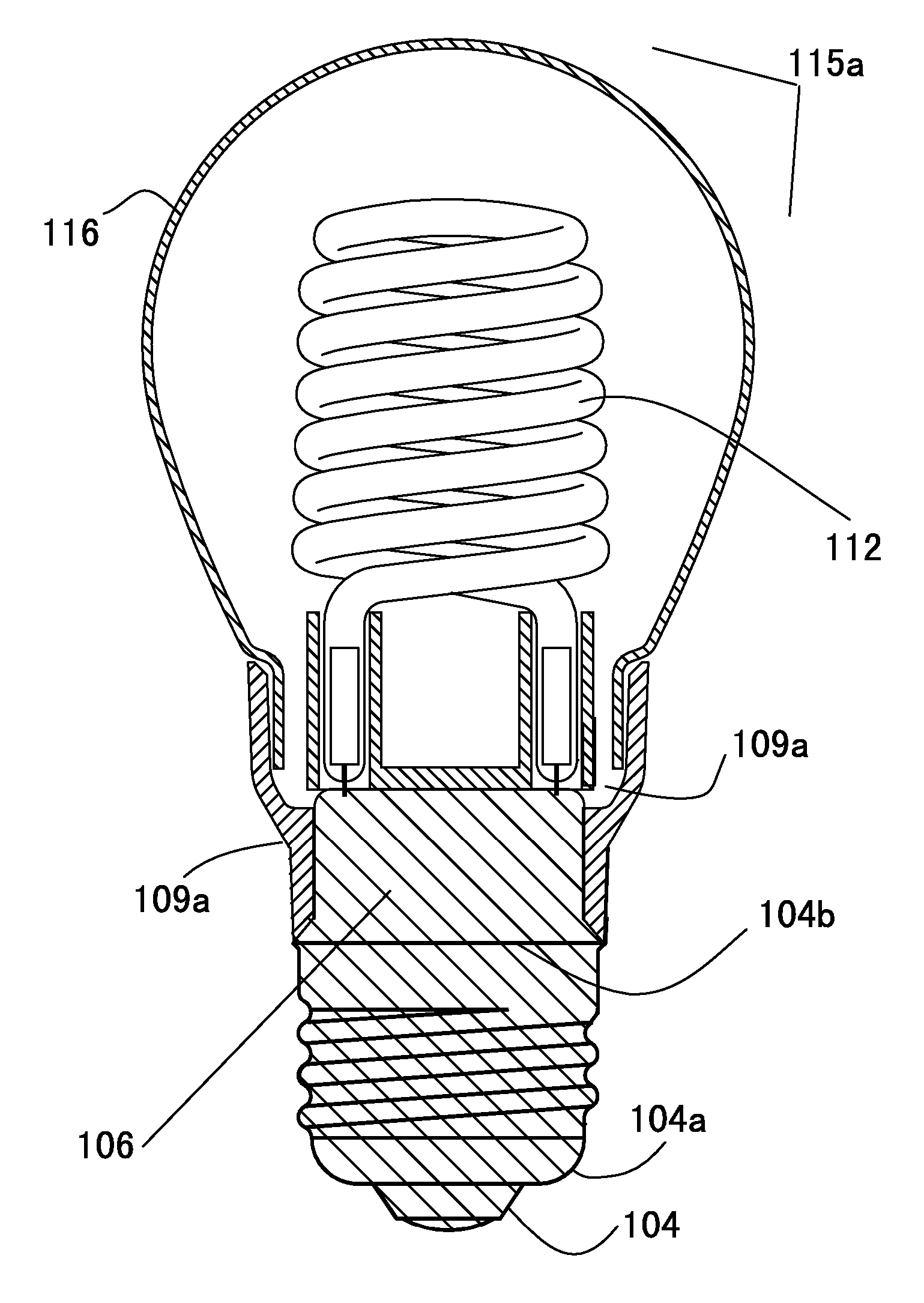
[0122] The first embodiment the present invention provides a CCFL device that has an integral ballast assembly attached with a lamp filament support. Said integral ballast assembly is formed by filling a heat-conductive compound within a detachable mold so that the entire space between the electronic driver and the lamp base are filled with the heat-conductive compound air-tightly. As a detachable and water-tight mold of a pre-determined shape is used to fill the heat-conductive compound, there is no need for a housing to enclose the electronic driver, as the assembly of heat-conductive compound forms its own surfaces after detached from the mold. It is preferred that at least one surface of the assembly of heat-conductive compound connecting to the shell of the lamp base is exposed to air, so that the heat from the assembly can be dissipated directly into the atmosphere. A metallic container connection member is also preferred as it is insulated from the metallic shell of the lamp ...

Example

Embodiment 2

[0142] In another preferred embodiment of the present invention, both of the lamp filament support member and the container connection member are attached integrally with the integral ballast assembly by using a specially designed mold. Before the heat-conductive compound is filled inside the mold, the lamp filament support member, the container connection member, the electronic driver and the lamp base are all securely disposed inside. At the same time, the electronic driver is coupled to at least two insulated portions of the shell of the lamp base.

[0143] In order for the lamp filament support member to be securely placed inside the mold, it is fabricated with at least one leg on the side facing away from the CCFL filament, and said at least one leg has a sufficient length to reach the inner bottom of the shell of the lamp base so that it can fix its position within the mold before the heat-conductive compound is filled inside. Alternatively, the lamp filament suppor...

Example

Embodiment 3

[0154] Another embodiment of the present invention provides for forming a CCFL device which does not have a container connection member and therefore looks almost the same as an ordinary incandescent light bulb, as its entire surface above the month line of the lamp base is the surface of the light-transmitting container. This is achieved by affixing the CCFL filament to a smaller lamp filament support member that is attached integrally with the integral ballast assembly. However, a special mold is used to form a circular cavity around the month line of lamp base, so that bottom of the light-transmitting container can be inserted into this circular cavity and is attached rigidly with the lamp base by using a bonding agent that comprises silicone adhesive, low melting point soldering glass or other heat-enduring adhesives.

[0155] Referring to FIG. 15(a), a small filament support member 130 is fabricated with a plurality of legs 130a and 130b. Referring to FIG. 15(b), int...


PUM


Abstract

A CCFL device using a heat-conductive compound that may also be light-transmitting to embed both its heat generating components, i.e., the electronic driver and the CCFL filament, so that there is no air trapped between these two heat sources and the outer surface of the device. The heat-conductive compound also forms its own surfaces that are exposed directly to air, so that the heat generated by the CCFL filament and the electronic driver is dissipated swiftly into the atmosphere. One embodiment of the present invention attaches the lamp filament support member to the integral ballast assembly, so it is no longer connected to the light-transmitting container in order to support the CCFL filament, thereby simplifies the manufacturing process significantly.

Description

BACKGROUND OF THE INVENTION [0001] The present invention pertains particularly to an improved cold cathode fluorescent lamp (CCFL) device comprising at least one elongated CCFL that is bent into a pre-determined shape such as a spiral, double-spiral, multi-Us, and etc. The CCFL device of the present invention uses a heat-conductive compound comprising a synthetic material such as an epoxy, a resin or a silicone to embed its CCFL filament and its electronic driver, so that there is no air trapped between these respective heat sources and the outer surface of the device. The heat-conductive compound also forms its own surfaces that are exposed directly to air, so the heat generated by the driver is dissipated swiftly into the atmosphere. The lamp filament support member of the device is attached to the integral ballast assembly instead of the light-transmitting container, thereby simplifying the manufacturing process significantly. [0002] A fluorescent lamp is a low pressure mercury v...

Claims


Application Information

Patent Timeline
IPC IPC(8): H01K1/50
CPCH01J5/54H01J61/70H01J61/52H01J61/327
Inventor KWONG, HENRY YUK HO
Owner KWONG HENRY YUK HO
Why Eureka
Try Eureka