

Functional fluorescent dyes
Inactive Publication Date: 2005-08-16
3M INNOVATIVE PROPERTIES CO
View PDF26 Cites 2 Cited by
- Summary
- Abstract
- Description
- Claims
- Application Information
AI Technical Summary
Benefits of technology
[0049]The dyed polymers of the invention can be used in coating compositions. An advantage of the invention is that the fluorescent dyes can be used in detecting the uniformity and thickness of the coating. A further advantage is that the fluorescent dyes provide stable, non-leaching color that can be used for decorative purposes.
[0050]Coating compositions comprising the dyed fluoropolymers of the invention can further comprise a solvent. Any solvent in which the dyed polymer dissolves to a suitable degree, which does not deleteriously affect the substrate, and which does not leave a harmful residue can be used. It is preferable, however, to use the same solvent that was used in the polymerization reaction. Therefore, preferences for coating solvents are the same as the preferences stated for polymerization solvents.
[0051]Typically, the coating composition comprises up to about 50 weight percent dyed fluoropolymer (preferably up to about 35 weight percent; most preferably up to about 28 weight percent). The resulting coatings are generally less than about 3 mils (0.08 mm) thick, but the desired thickness depends upon the specific application. Thicker or thinner coatings can be prepared if desired. The coating composition can be applied to a substrate or article using any suitable means known in the art such as, for example, brushing, dipping, spraying, and flow coating.
[0052]Circuit board components and assemblies can be coated with the present dyed coating compositions to form films (sometimes referred to as conformal coatings), which insulate them from contaminants and preserve their electronic functions. Circuit board assemblies can be coated before or after the components have been mounted, but they are typically conformally coated after they have been completely assembled and soldered. Proper coverage and uniformity of the conformal coating over the assembly is critical for effective protection of the assembly. Following application of the coating composition to the assembly, the composition is dried and / or cured to yield the resultant film.
[0053]The addition of the fluorescent dyes of the invention into conformal coating compositions aids in the quality assurance inspection of the circuit board assembly for proper coverage of the coating. The fluorescent dyed polymers of the invention can be readily observed by the human eye using, for example, “black light” or on-line with an electro-optical device. The coating thickness (or coating weight) can be measured on-line using techniques in which the dye is excited by optical radiation and the thickness of the coating is determined by the magnitude of the emitted fluorescent radiation.
[0054]The dyed coating compositions of the invention can also be used in many other applications where it is desirable for the coating to have color for either decoration or detection. An advantage of the present dyed coating compositions is their high wetfastness properties, which are attributed to the covalent bonding of the dye to the polymer matrix. This is an advantage over coating compositions containing dyes fixed through adsorption or blending and makes the dyed coating compositions of the invention highly suitable for applications where toxicity is an issue such as, for example, in medical and food packaging applications.EXAMPLES
Problems solved by technology
It can be difficult, however, to determine the integrity and uniformity of the conformal coating when it is coated on an assembly.
Most fluorescent dyes, however, have poor or limited solubility in certain polymer matrixes.
For instance, most fluorescent dyes have poor or no compatibility with fluorochemical monomers and polymers.
This results in poor color quality and dye bleed and little or no color entrainment into the resulting fluoropolymer.
Fluoropolymers containing dyes are therefore typically not used when leaching and toxicity issues are of concern (for example, in food packaging and medical applications).
There is also little advantage in adding most dyes to fluoropolymer conformal coatings since the dyes typically do not entrain uniformly throughout the coating such that they are useful during quality control inspection.
Method used
View moreImage
Smart ImageViewing Examples

Examples
example 1
[0118]A 600 mL Parr reactor (available from Parr Instrument Co., Moline, Ill.) was charged with MeFBSEA (146.30 g; 0.36 moles), MeFBSEMA (10.03 g; 0.023 moles), BMA (3.34 g; 0.023 moles), LMA (5.85 g; 0.023 moles), MAA (1.67 g; 0.020 moles) and AD-1 (0.011 g). Upon dissolution of the charges, LUPEROX (9.24 g) and HFE-7100 (440.80 g) were added. The reactor was then sealed and degassed four times, by pulling a vacuum of 5-10 psig (34-68 kPa) and then purging with nitrogen. The reactor temperature was then elevated and held at 80° C. for about 24 hours. The resulting reaction mixture was filtered. The resulting filtered solution was used to coat substrates for testing.
Login to View More PUM
| Property | Measurement | Unit |
|---|---|---|
| Fraction | aaaaa | aaaaa |
| Fraction | aaaaa | aaaaa |
| Volume | aaaaa | aaaaa |
Abstract
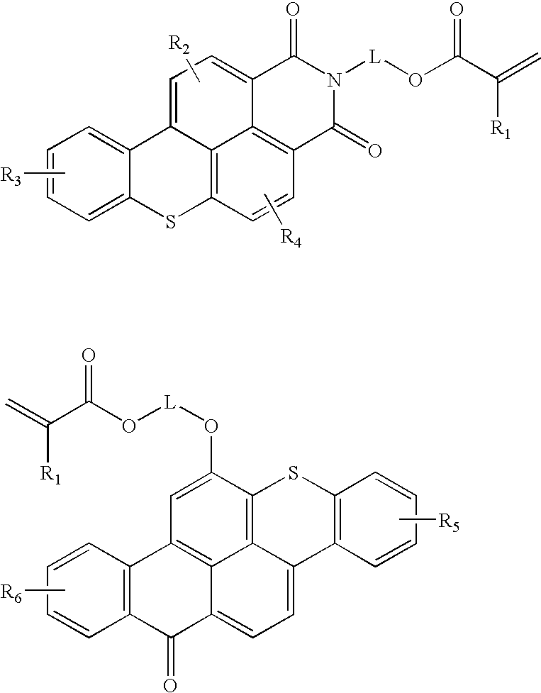
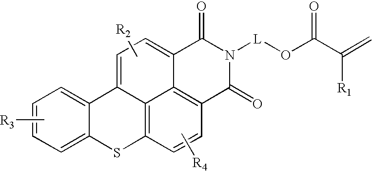
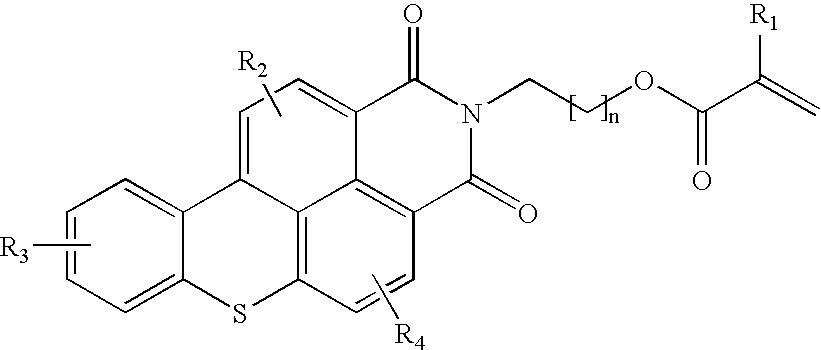
Fluorescent functional dyes represented by the following formulas: wherein R1 is hydrogen or methyl; R2, R3, R4, R5, and R6 are each independently selected from the group consisting of hydrogen, alkyl, aryl, alkoxy, aralkyl, alkaryl, halo, and trifluoromethyl; and L is a straight chain or branched chain alkylene containing 3 to about 15 carbon atoms, the alkylene group optionally containing one or more catenary heteroatoms.
Description
FIELD[0001]This invention relates to fluorescent dyes and, in other aspects, to polymer coatings and films comprising the dyes.BACKGROUND[0002]Conformal coatings are protective coatings that conform to the surface of electronic components and circuit board assemblies. Properly applied conformal coatings can increase the working life of the assemblies by protecting its components and the board itself. Proper coverage and uniformity of the conformal coating over the assembly is critical for effective protection of the assembly. It can be difficult, however, to determine the integrity and uniformity of the conformal coating when it is coated on an assembly. Therefore, the conformal coating material is sometimes doped with a fluorescent dye or “tracer” to aid in the quality assurance inspection of the assembly for proper coverage.[0003]Fluorescent dyes such as, for example, thioxanthene compounds, work well for imparting color to certain plastic materials such as, for example, polymetha...
Claims
Login to View More Application Information
Patent Timeline
 IPC IPC(8): C09B57/14C09B23/02C09B23/00C09B57/00C07D495/06C08F20/38C09B5/02C07D335/04C09B11/28C09B57/08C09D7/12C09D201/00H05K1/02H05K3/28
CPCC09B23/02C09B57/14H05K3/285H05K1/0269H05K2203/161C09B57/00C09K11/02C07D498/02
InventorOLSON, DAVID B.
Owner3M INNOVATIVE PROPERTIES CO