CCFL with a gaseous heat-dissipation means

a fluorescent lamp technology, applied in the field of low pressure mercury vapor gas discharge fluorescent devices, can solve the problems of tungsten wire easily breaking, and hcfl having a relatively short life, so as to achieve high intensity illumination

Inactive Publication Date: 2007-02-08
KWONG HENRY
View PDF26 Cites 6 Cited by
  • Summary
  • Abstract
  • Description
  • Claims
  • Application Information

AI Technical Summary

Benefits of technology

[0034] In order to overcome the afore-described shortcomings and difficulties of the CCFL devices aiming for general lighting uses, an object of the present invention is to provide an improved CCFL gas discharge device with a compact form factor, that has a similar shape and dimension of a conventional incandescent light bulb, that can overcome the heat dissipation difficulties for both the CCFL filament and the electronic driver, so that it can generate high intensity illumination when operating at high electricity power input.

Problems solved by technology

The stress on its tungsten wire during the lamp's on-off instant is so severe that when the device is flashing continuously, or when it is turned on and off frequently, the tungsten wire breaks easily.
The tungsten wire of HCFL also has a limited life as it weakens continuously by its own evaporation, same as the tungsten wire of an ordinary incandescent light bulb.
These disadvantages render the HCFL a relatively short-life lighting device, with life span of usually a few thousands hours.
Another disadvantage of the HCFL is that its light output cannot be dimmed smoothly, as the tungsten wire needs a stable and high temperature to be maintained in order for it to continuously emit electrons from the electron emissive layer.
The HCFL can therefore only be dimmed stepwise using complicated and expensive electronic circuitry.
Despite the key disadvantage of having a fragile, long and thin lamp filament, the CCFL wastes no power to heat up the electrode during the start of the lamp.
Nevertheless, the reality is that the CCFL is so far only frequently used in the back light module for the viewing screen of note book computers, LCD TVs, flat panel displays, and for the exit signs, where the electricity power required for these applications are only several watts.
The most important shortcoming of the conventional CCFL device is that it cannot normally operate at a high electricity power input due mainly to over heating.
The luminous efficacy of the CCFL decreases sharply when the body temperature of the lamp filament rises with the increase of electricity power input, particularly when the CCFL device lacks an efficient heat dissipation means.
Yet at such a lower electricity power input, the length of the CCFL is not long enough to allow the CCFL to operate with sufficiently high cathode-fall voltage, so that the ability of the CCFL to pull electrons from the “cold” cathodes are not optimized, resulting in significantly lower light output efficiency than the HCFL.
If the tubing diameter is too small, the mercury plasma will absorb an excessively higher proportion of the electrons, thereby weakens the mercury plasma's overall output of ultraviolet radiation, and ultimately reduces the device's light generation efficiency.
Due to the physical fragility of the elongated lamp filament of the CCFL, a CCFL device cannot normally be acceptable for general lighting applications in a bare lamp form factor without a light-transmitting container or a layer or coating of light-transmitting mater substantially embedding the lamp filament inside, mainly for safety reasons.
Moreover, being coverless also raises another unpleasant shortcoming, as phototactic insects would be trapped and died inside the narrow pitches of the exposed lamp filament spiral.
However, the CCFL filament generates considerable heat under an enclosed environment where heat is not easily dissipated.
Above this temperature range, the excessive heat will cause the mercury ions to become overly active so that the mercury vapor pressure within the CCFL increases.
If this pressure is too low, few mercury molecules are excited, meaning insufficient ultraviolet radiation falls on the phosphor layer.
One more shortcoming of the CCFL is that the electronic driver has a high-voltage transformer which is highly vulnerable to heat damages.
For a conventional CCFL device, the heat dissipated by the CCFL filament always cause the electronic driver to fail as the latter usually connects to the CCFL electrodes at a short distance.
Such excessive heat generated by the CCFL, together with the heat generated by the components of electronic driver, if not being properly dissipated, affects the life span of the electronic driver adversely.
Unlike the HCFL, the electronic driver of the CCFL is more vulnerable to damages by overheating because it comprises a high-voltage transformer in its circuitry that generates about 500-2,500 volt of AC electricity at a frequency of 10k-150 kHz.
Because of the high voltage, this transformer needs extra insulation and effective heat dissipation means, otherwise it fails easily and destroys the entire electronic driver.
Owing to the bulkiness of such conventional design, it needs a large plastic driver housing, which becomes even larger because of the housing itself has a wall thickness of at least 1.5 mm on its entire circumference.
Another disadvantage of the conventional CCFL device that uses a driver housing to connect to both the light-transmitting and the lamp base is that the driver housing can not be made of metal, as it will be electrically conductive after attached to the lamp base.
However, a plastic or ceramic driver housing is a poor heat conductor, especially when air is trapped inside its unoccupied space.
This causes the electronic driver inside to be easily over-heated.
The short life span of the HCFL is therefore causing significant difficulties owing to the frequent replacement needs, as well as the high positions that are difficult to reach.
Moreover, these HCFL devices are not dimmable by ordinary wall dimmers.

Method used


Image

  • CCFL with a gaseous heat-dissipation means
  • CCFL with a gaseous heat-dissipation means
  • CCFL with a gaseous heat-dissipation means

Examples


embodiment 1

[0095] The first embodiment of the present invention provides a novel heat dissipation means for an CCFL device that is comprising: an hermetically sealed light-transmitting container housing at least one CCFL filament inside; an electronic driver providing high-frequency and high-voltage electricity is electrically connected to the electrodes of the CCFL filament, and is also connected to a lamp base that receives external electricity from a electrical socket, and said container is filled with a high thermal conductivity gas that has better thermal conductivity than air, so that the heat generated from the CCFL filament can be dissipated swiftly into the atmosphere through the surface of the light-transmitting container.

[0096] In the embodiment immediately above, and in other embodiments described below, there are many obvious variations for forming said CCFL device. For instance, the electronic driver can be a DA / AC or AC / AC converter, i.e., the input electricity current can be e...

embodiment 2

[0107] Another embodiment of the present invention provides a novel method stopping the helium or hydrogen gases leaking away from the light-transmitting container, and also stopping them from diffusing into the inside of the CCFL lamp filament which is of lower partial helium or hydrogen pressure than the inside of the light-transmitting container. Helium and hydrogen can normally diffuse through the glass container and the hermetical seals between the glass container and other lamp body surfaces. According to the present invention, soda lime glasses is used for the light-transmitting container and for the glass envelope of the CCFL filament, as the helium and hydrogen permeation rates through soda lime glass are several thousand times less than those through quartz, borosilicate and Pyrex glass under room temperature. Moreover, for the other parts of the lamp body, such as the container connection member, metal such as aluminum or copper is preferred, as the helium and hydrogen ga...

embodiment 3

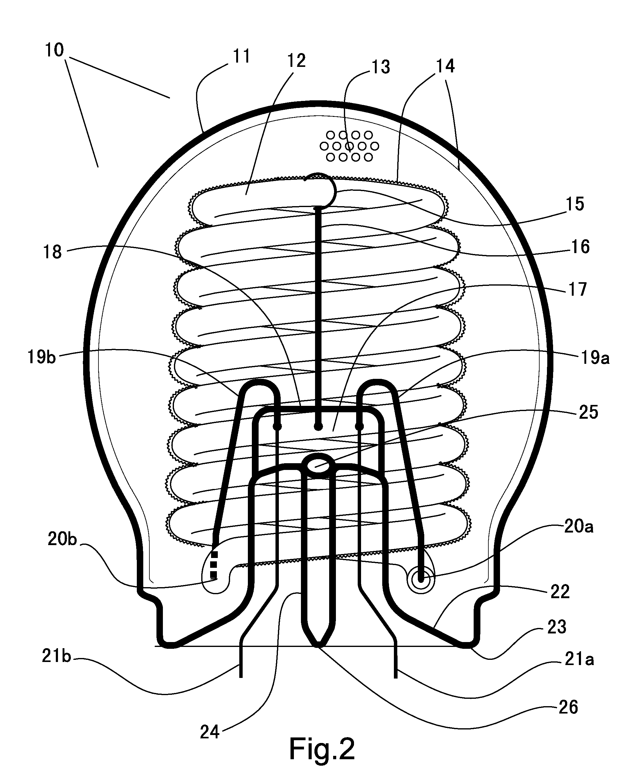
[0111] Another embodiment of the present invention provides a novel means to affix the CCFL lamp filament within the light-transmitting container in a secured and vibration-proof manner, and at the same time, to allow air be evacuated from, and a high thermal conductivity gas be filled inside said container. This is accomplished by affixing the CCFL lamp filament to a traditional lamp foot that has been used for the incandescent light bulbs for over a century. A lamp foot is formed from a short and hollow glass tube of outer diameter 5-10 mm and inner diameter 3-7 mm so that the tube body is about 1 mm thick. Owing to the massive demand, automated machines are available to make lamp foots in large volumes and at low cost, and existing automated machines for bonding lamp foots to the light-transmitting containers are abundant.

[0112] Commercially available lamp foots have many different formats, but all have three common features, i.e., (1) an inner glass exhaust tube along its axis,...


PUM


Abstract

A CCFL device has at least one CCFL inside a hermetically-sealed light-transmitting container that is filled with a high thermal conducitivity such as helium. A heat-conducting compound forms with the electronic driver and the lamp base into an integral ballast assembly, so that no housing for the driver is needed. The integral ballast assembly connects electrically to the electrodes of the CCFL, receives electricity through its lamp base, and uses a container connection member to connect to the light-transmitting container.

Description

CROSS-REFERENCE TO RELATED APPICATIONS [0001] This application is a continuation of the U.S. patent application Ser. No. 11 / 467,653, filed by Henry Yuk Ho Kwong on Aug. 28, 2006STATEMENT REGARDING FEDERALY SPONSORED RESEARCH OR DEVELOPMENT [0002] Not Applicable REFERENCE TO SEQUENCE LISTING, A TABLE, OR A COMPUTER PROGRAM LISTING COMPACT DISC APPENDIX [0003] Not Applicable BACKGROUND OF THE INVENTION [0004] The present invention pertains generally to the low pressure mercury vapor gas discharge fluorescent devices, and more particularly to an improved cold cathode fluorescent lamp (CCFL) device comprising at least one elongated CCFL that is bent into a pre-determined shape such as a spiral, double-spiral, cone, serpentine, 1-U, 2-Us, multi-Us, and etc. Said CCFL is enclosed inside a light-transmitting container which is hermetically sealed and filled inside with a high thermal conductivity gas that has thermal conductivity better than air. Its electronic driver may also be embedded ...

Claims


Application Information

Patent Timeline
Patent Type & Authority Applications(United States)
IPC IPC(8): H01J5/50
CPCH01J5/54H01J61/34H01J61/327H01J9/34
Inventor KWONG, HENRY
Owner KWONG HENRY
Why Eureka
Try Eureka