Stereoscopic visualization device for patient image data and video images

a visualization device and image data technology, applied in the field of medical video imaging, can solve the problems of difficult estimation or inferential depth information of the unit, only providing the doctor and/or any observer with a flat projection, and achieving the effects of improving flexibility, simplifying and quickly calculating image rendering, and improving resolution

Active Publication Date: 2008-12-09
BRAINLAB
View PDF25 Cites 33 Cited by
  • Summary
  • Abstract
  • Description
  • Claims
  • Application Information

AI Technical Summary

Benefits of technology

[0007]It is possible to visually provide the entire informational content of the three-dimensional patient image data sets. To this end, an auto-stereoscopic monitor can be used that provides the observer with a three-dimensional image, without requiring additional aids such as special spectacles, for example. The auto-stereoscopic monitor can be provided with the patient image data in a suitable way, such that the patient image data appear three-dimensional to the observer.
[0008]If the camera means is a stereoscopic camera means, the data captured by the camera means of the patient's exterior also can be manipulated such that the monitor, provided with said data, generates a stereoscopic and / or three-dimensional video image of the patient's body part. Because the data can be positionally assigned by means of the navigation system, the two images can be superimposed such that a three-dimensional view is created on the monitor, which allows the observer to simultaneously observe the patient's body part by way of exterior and interior features and, thus, to also obtain depth information.
[0009]Auto-stereoscopic monitors are available and can be adapted to the requirements of the application. There are so-called parallax displays that are based on a two-dimensional image plane, wherein diffuse light can be actively focused and aligned. So-called parallax barrier systems use a kind of aperture mask, e.g., an opaque layer in front of the image surface that is interrupted by regular slits, wherein a defined image region can be presented depending on the angle of view. Other systems also can be used with the present invention, including lens-based systems in which the views are separated before the screen by lens elements. Round lenses can be used (full parallax) or semi-cylindrical optical lenses that use sub-pixel control (slanted lenticular sheets) provide improved resolution when aligned obliquely. Further, oblique sub-pixel arrays avoid moiré effects and black transitions. It is also possible to use alternative parallax systems, e.g. prism systems or polarizing filters.
[0010]The camera means can include a single camera. In one embodiment, the camera means includes at least two cameras that are arranged on a rear or back side of the image display device (e.g., on the opposite side to the screen) and wherein a distance between the two cameras can be adjusted to a predetermined distance range between the observer and the monitor. The camera means also can include movable cameras. The movable cameras enable one to set an intersecting region of the fields of vision of the cameras in accordance with the distance between the cameras and the object observed and / or in accordance with the distance between the observer and the monitor. Thus, the entire array, as well as the software, can be set to a typical scenario prior to use, wherein corresponding predetermined fixed values or ranges of values can be used. In this way, for example, image rendering can be simplified and quickly calculated. Further, the movable cameras increase flexibility with respect to the distance between the portable image display device and the patient.
[0012]Further, an observer tracking unit can be assigned to the monitor to create a so-called active system that tracks the observation zone(s) of the observer. The image processing unit can display an image on the monitor that develops its observation zone(s) at each observer location or at each tracked observer location. Such an “active” system that monitors a location of the observer provides the observer with the best stereoscopic image at the observer's location.

Problems solved by technology

A disadvantage of this portable screen-camera unit is that the physician and / or any observer is only provided with a flat projection, i.e., a two-dimensional view.
Depth information is difficult to estimate or infer from the unit.

Method used


Image

  • Stereoscopic visualization device for patient image data and video images
  • Stereoscopic visualization device for patient image data and video images
  • Stereoscopic visualization device for patient image data and video images

Examples


Embodiment Construction

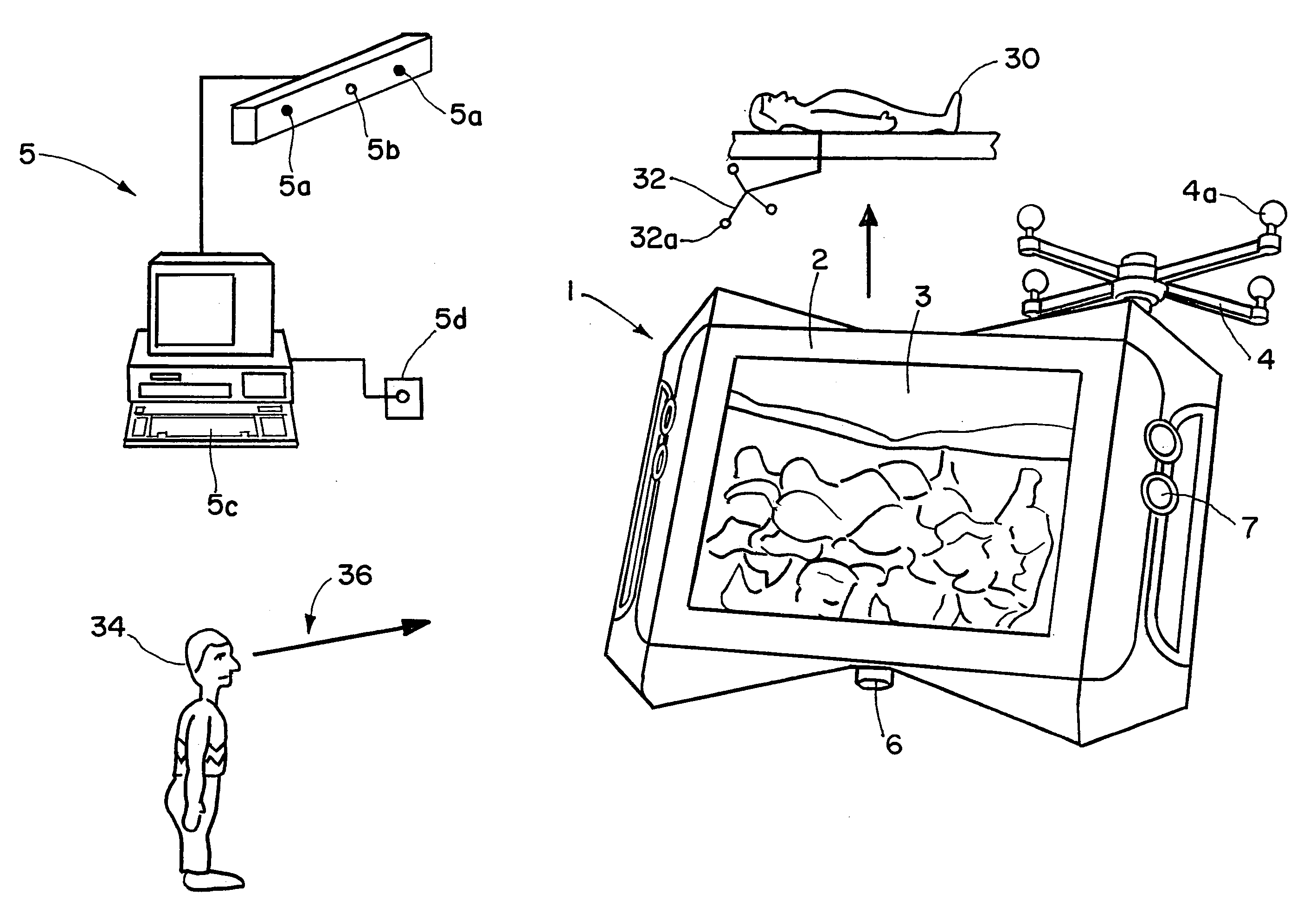
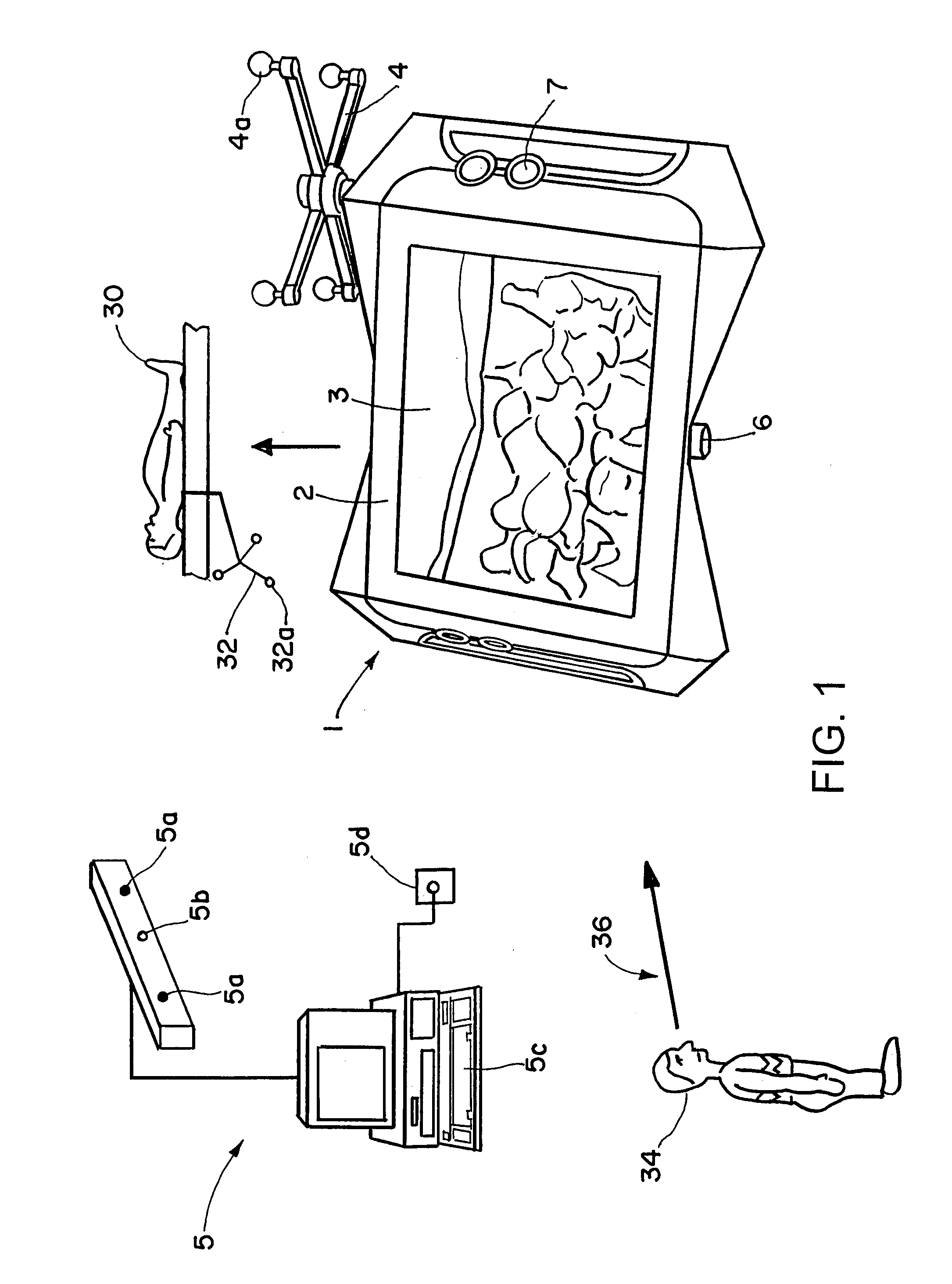
[0021]Referring to FIG. 1, an image display unit 1 is shown in a perspective view from the front. The image display unit includes a casing 2, which is fitted on a front side with a screen 3. The screen 3 is an auto-stereoscopic screen or monitor, and in the present case a partially covered patient's back is shown on its display with the spinal column beneath.

[0022]A reference star 4 with markers 4a is shown on top of the casing 2 and enables a position of the image display unit 1 in a localizing space of a navigation system 5 to be established. Thus, a position of the cameras 7 and 8 (shown in FIG. 2 on the rear side of the image display unit 1) also can be established in the navigation system's localizing space. More particularly, since the patient 30 is also tracked by the navigation system 5 via reference star 32 with markers 32a, the video image of the cameras 7 and 8 also can be spatially assigned in the navigation system 5 and displayed in the correct spatial positional relati...


PUM


Abstract

A system for visually combining patient image data from transillumination and / or tomographic imaging methods and / or object image data with video images includes an image display device having an auto-stereoscopic monitor, at least one camera and a computer-assisted navigation system. The navigation system is operable to detect spatial positions of a part of the patient's body via a first tracking device attached to the body, and spatial positions of said image display device and / or said at least one camera via a second tracking device attached to the image display device or the camera, wherein the image display device and the at least one camera are assigned to each other and are formed as a portable unit.

Description

RELATED APPLICATION DATA[0001]This application is a continuation-in-part of U.S. Non-Provisional application Ser. No. 10 / 830,963 filed on Apr. 23, 2004 now U.S. Pat. No. 7,203,277, which claims priority to U.S. Provisional Application No. 60 / 489,750 filed on Jul. 24, 2003, both of which are incorporated herein by reference in their entirety.FIELD OF THE INVENTION[0002]The present invention relates to medical video imaging and, more particularly, to a portable device for visually combining patient image data from transillumination and / or tomographic imaging methods and / or object image data with video images.BACKGROUND OF THE INVENTION[0003]EP 1 321 105 B1 discloses a portable screen-camera unit that includes a camera mounted on a rear side of a screen. A physician can hold the portable screen together with the corresponding camera in front of a patient (e.g., in front of a particular body part). By displaying in combination patient image data from transillumination and / or tomographic...

Claims


Application Information

Patent Timeline
Patent Type & Authority Patents(United States)
IPC IPC(8): G03B29/00
CPCG03B41/00A61B6/462A61B6/5235
Inventor BIRKENBACH, RAINERSCHMIDT, ROBERTWOHLGEMUTH, RICHARDRO.BETA.NER, HOLGER-CLAUSFRIELINGHAUS, NILSSCHAFFRATH, CLAUSWORLEIN, SWEN
Owner BRAINLAB
Why Eureka
Try Eureka